Design Guide | iC2-Micro Frequency Converters Mechanical Installation Considerations
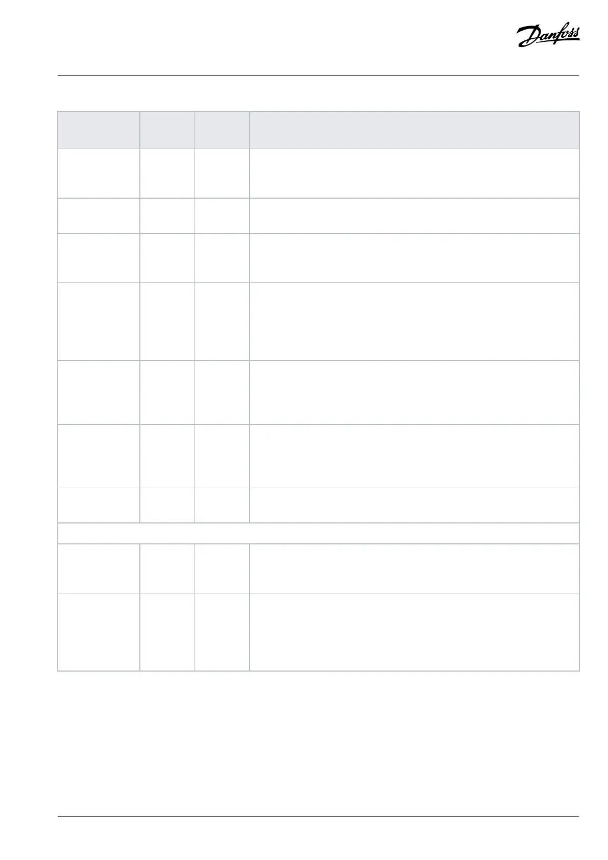
Table 47: Maintenance Schedule for Air-cooled Drives (continued)
Component Inspection
interval
(1)
Service
schedule
(2)
Preventive maintenance actions
Control panel 1 year – Check that the display pixels are intact. Check the event log for warnings and faults.
Repetitive events are a sign of potential issues. If necessary, contact a local service
center.
Drive cooling ca-
pacity
1 year – Check for blockages or constrictions in the air passages of the cooling channel. The
heat sinks must be free of dust and condensation.
Cleaning and fil-
ters
1 year – Clean the interior of the enclosure annually, and more frequently if necessary. The
amount of dust in the filter or inside the enclosure is an indicator for when the next
cleaning or filter replacement is required.
Fans 1 year 3–10 years Inspect the condition and operational status of all cooling fans. With the power off,
the fan axis should feel tight, and spinning the fan with a finger, the rotation should
be almost silent and not have abnormal rotation resistance. When in RUN mode,
fan vibration, excessive or strange noise is a sign of the bearings wearing, and the
fan must be replaced.
Grounding 1 year – The drive system requires a dedicated ground wire connecting the drive, the out-
put filter, and the motor to the building ground. Check that the ground connec-
tions are tight and free of paint or oxidation. Daisy-chain connections are not al-
lowed. If applicable, braided straps are recommended.
Power cables and
wiring
1 year – Check for loose connections, aging, insulation condition, and proper torque to the
drive connections. Check for proper rating of fuses and continuity check. Observe if
there are any signs of operation in a demanding environment. For example, discol-
oration of the fuse housing can be a sign of condensation or high temperatures.
Vibration 1 year – Check for abnormal vibration or noise coming from the drive to ensure that the en-
vironment is stable for electronic components.
Spare parts
Spare parts 1 year 2 years Stock spares in their original boxes in a dry and clean environment. Avoid hot stor-
age areas. Electrolytic capacitors require reforming as stated in the service sched-
ule. The reforming must be performed by trained service personnel.
Exchange units
and units stored
for long periods
before commis-
sioning
1 year 2 years Visually inspect for signs of damage, water, high humidity, corrosion, and dust
within the visual field of view without disassembly. The exchange units with
mounted electrolytic capacitors require reforming as stated in the service schedule.
The reforming must be performed by trained service personnel.
1) Defined as the time after the commissioning/startup or the time from the previous inspection.
2) Defined as the time after the commissioning/startup or the time from the previous service schedule actions.
6.6.3 Service Access
To ensure planned and extended drive lifetime, Danfoss recommends regular inspection and service actions for the drive, motor, system,
and cabinet/enclosure. To prevent breakdown, danger, and damage, examine, for example, the tightness of terminal connections and
dust build-up in the drive at regular intervals depending on the operating conditions.
If the Danfoss drive is operated in environments near the limit or beyond design boundaries, maintenance of the drive is required.
Danfoss A/S © 2024.08 AJ402315027937en-000401 / 130R1239 | 67