Design Guide | iC2-Micro Frequency Converters Specifications
Table 39: dU/dt Data for iC2-Micro Frequency Converters (continued)
Enclosure size Power [kW(hp)] Cable length
[m(ft)]
Mains voltage
[V]
Rise time [μ
sec
] U
PEAK
[kV] dU/dt [kV/μ
sec
]
MA05a 22 (30) 5 (16.4) 3x400 0.108 0.66 4.89
MA05a 22 (30) 50 (164) 3x400 0.404 1.02 2.02
MA05a 22 (30) 5 (16.4) 3x480 0.148 0.78 4.26
MA05a 22 (30) 50 (164) 3x480 0.404 1.19 2.36
4.9 Derating
4.9.1 Overview of Derating
Consider derating if the drive is challenged under some special conditions. Derating of the drive includes:
l Manual derating.
l Automatic derating.
4.9.2 Manual Derating
Manual derating must be considered for:
l Air pressure – for installation at altitudes above 1000m (3281ft).
l Motor speed – at continuous operation at low RPM in constant torque applications.
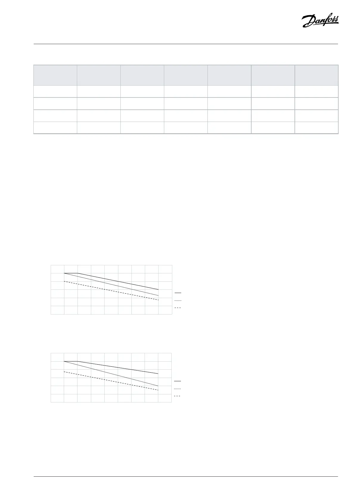
l Ambient temperature – above 40°C (104°F), for details, see the following figures.
4 6 8 10 12 14 16 18
e30bv117.10
(kHz)
40 °C (104 °F)
50 °C (122 °F)
55 °C (131 °F)
Figure 14: Derating of Output Current Versus Switching Frequency (MA01c 1x100–120 V AC and 1x200–240VAC)
4 6 8 10 12 14 16 18
e30bv118.10
(kHz)
40 °C (104 °F)
50 °C (122 °F)
55 °C (131 °F)
Figure 15: Derating of Output Current Versus Switching Frequency (MA02c 1x100–120 V AC and 1x200–240VAC)
Danfoss A/S © 2024.08 AJ402315027937en-000401 / 130R1239 | 53