Design Guide | iC2-Micro Frequency Converters Specifications
All control inputs and outputs are PELV galvanic isolated from supply voltage and other high-voltage terminals, unless otherwise
specified.
4.2.5.2 Digital and Pulse Input
Control inputs and outputs are PELV galvanically isolated from supply voltage and other high-voltage terminals, unless otherwise
specified.
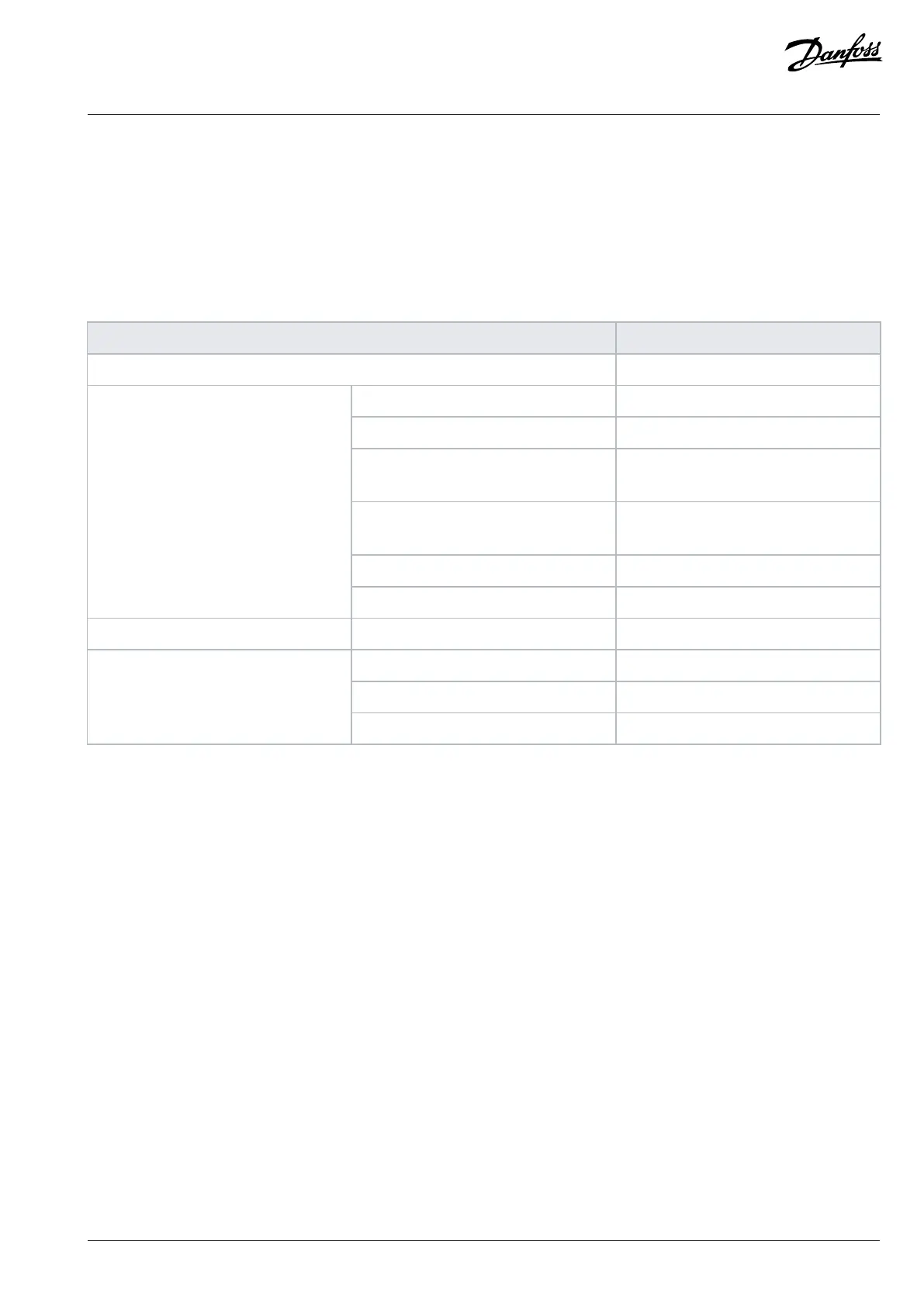
Table 22: Digital and Pulse Input
Function Data
Terminal number T13, T14, T15
(1)
, T17, and T18
(2)
.
Logic Selectable PNP or NPN
Voltage levels 0/24V
PNP • 0: <5VDC
• 1: >11VDC
NPN • 0: >19VDC
• 1: < 13VDC
Maximum allowed voltage 28VDC
Digital input
Input resistance Approximately 4kΩ
Thermistor input PTC
(3)
According to DIN 44081/DIN 44082
Pulse frequency range 1Hz–32kHz
Minimum duty cycle 40%
Pulse input
Accuracy 1% of full scale
1) T15 is selectable for either digital input, digital output, or pulse output. The default setting is digital input.
2) T18 can also be used for pulse input.
3) External insulation of the sensor is required to comply with PELV.
4.2.5.3 Digital and Pulse Output
Control inputs and outputs are PELV galvanically isolated from supply voltage and other high-voltage terminals, unless otherwise
specified.
Danfoss A/S © 2024.08 AJ402315027937en-000401 / 130R1239 | 41