Figure 48: Single-phase and 3-phase Wire Connections
2. Depending on the configuration of the equipment, connect the input power to the mains input terminals or the input
disconnect.
3. Ground the cable in accordance with the grounding instructions, see 7.4.2 Power Cables and Grounding.
7.10.4 Control Terminal Types
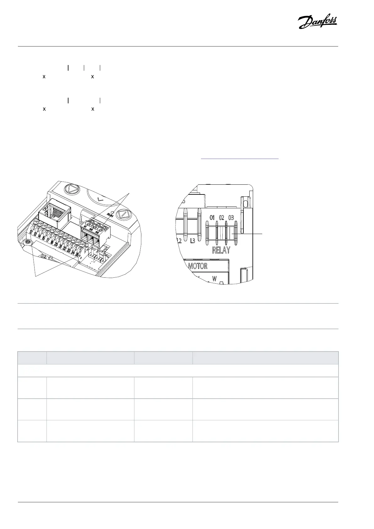
Figure 49: Control Terminal Numbers and Locations
1 Control I/O terminals 2 Serial communication
3 Relay
Table 55: Terminal Descriptions
Terminal Parameter Default setting Description
Digital I/O, pulse I/O
12 – +24VDC 24VDC supply voltage. Maximum output current is
100mA.
13 Parameter P 9.4.1.2 Terminal 13
Digital Input
[8] Start Digital input.
14 Parameter P 9.4.1.3 Terminal 14
Digital Input
[10] Reversing Digital input.
92 | Danfoss A/S © 2024.08 AJ402315027937en-000401 / 130R1239
Design Guide | iC2-Micro Frequency Converters Electrical Installation Considerations