Design Guide | iC2-Micro Frequency Converters Electrical Installation Considerations
I
M,N
(P 4.2.2.3)
I
M
f
OUT
= 2 x f
M,N
(P 4.2.2.4)
f
OUT
= 1 x f
M,N
f
OUT
= 0.2 x f
M,N
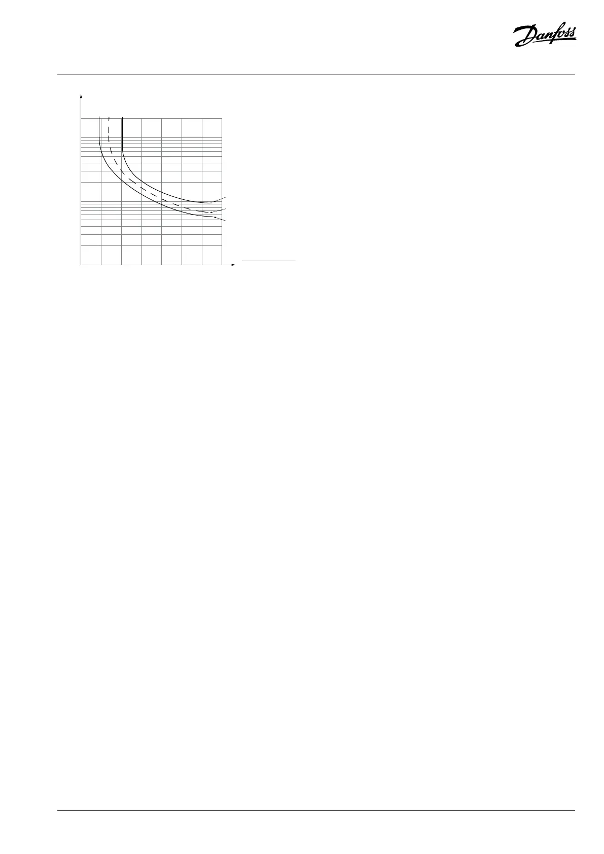
Figure 45: ETR
The X-axis shows the ratio between I
motor
and I
motor nominal
. The Y-axis shows the time in seconds before the ETR cuts off and trips the
drive. The curves show the characteristic nominal speed at twice the nominal speed and at 0.2 x the nominal speed. At lower speed, the
ETR cuts off at lower heat due to less cooling of the motor. In that way, the motor is protected from being overheated even at low speed.
The ETR feature calculates the motor temperature based on actual current and speed. The calculated temperature is visible as a readout
parameter in parameter P 4.1.5 Motor Thermal Load.
Externally connected sensors
Monitoring can be done by using analog input or digital inputs on the I/O board or with functional extension options. The sensors must
be either double isolated or have reinforced insulation between motor and drive control.
The analog input allows measurement of the temperature by using external sensors.
Using a digital input allows monitoring with a PTC sensor. The PTC must be connected from 24VDC to the digital input.
For more information on configuring the functionalities, refer to the application guide.
7.8 Extreme Running Conditions
Short circuit (motor phase to phase)
The drive is protected against short circuits by current measurement in each of the 3 motor phases or in the DC link. A short circuit
between 2 output phases causes an overcurrent in the drive. The drive is turned off individually when the short-circuit current exceeds
the allowed value (Fault 16, short circuit).
Switching on the output
Switching on the output between the motor and the drive is fully allowed and does not damage the drive. However, fault messages may
appear.
Motor-generated overvoltage
The voltage in the DC link is increased when the motor acts as a generator. This occurs in following cases:
l The load drives the motor (at constant output frequency from the drive).
l If the inertia moment is high during deceleration (ramp-down), the friction is low and the ramp-down time is too short for the
energy to be dissipated as a loss in the drive, the motor, and the installation.
l Incorrect slip compensation setting may cause higher DC-link voltage.
Danfoss A/S © 2024.08 AJ402315027937en-000401 / 130R1239 | 87