Design Guide | iC2-Micro Frequency Converters Electrical Installation Considerations
Figure 51: Correct Connection of the Cable Shield
The preferred method is to secure control and serial communication cables with shielding clamps provided at both ends to ensure the
best possible high-frequency cable contact.
If the ground potential between the drive and the PLC is different, electric noise could disturb the entire system. Solve this problem by
fitting an equalizing cable as close as possible to the control cable. Minimum cable cross-section: 16 mm
2
(6 AWG).
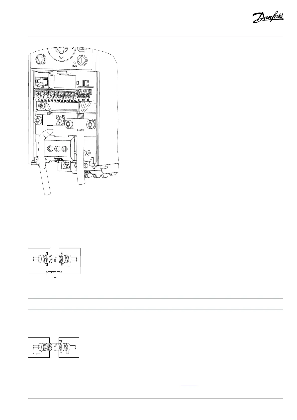
Figure 52: Shielding Clamps at Both Ends
1
Minimum 16 mm
2
(6 AWG)
2 Equalizing cable
With long control cables, ground loops may occur. To eliminate ground loops, connect the end of the shield to the ground with a 100nF
capacitor (keeping leads short).
Figure 53: Connection with a 100 nF Capacitor
To avoid EMC noise on serial communication, terminal 61 is connected to ground via an internal RC link. Use twisted-pair cables to
reduce interference between conductors. The recommended method is shown in Figure 54.
Danfoss A/S © 2024.08 AJ402315027937en-000401 / 130R1239 | 95