Design Guide | iC2-Micro Frequency Converters Specifications
The dimensions apply to both solid and stranded cables. Drives are designed for use of 70°C (158°F) rated copper cables. If nothing else
is stated, the ambient temperature of the drive matches the cable rating. Aluminum cables can be used from 35mm
2
onwards. Proper
connections must be secured by removing the oxide layer and applying joint compound.
NOTICE
Using a cable with the maximum allowed cross-section requires more effort during the installation.
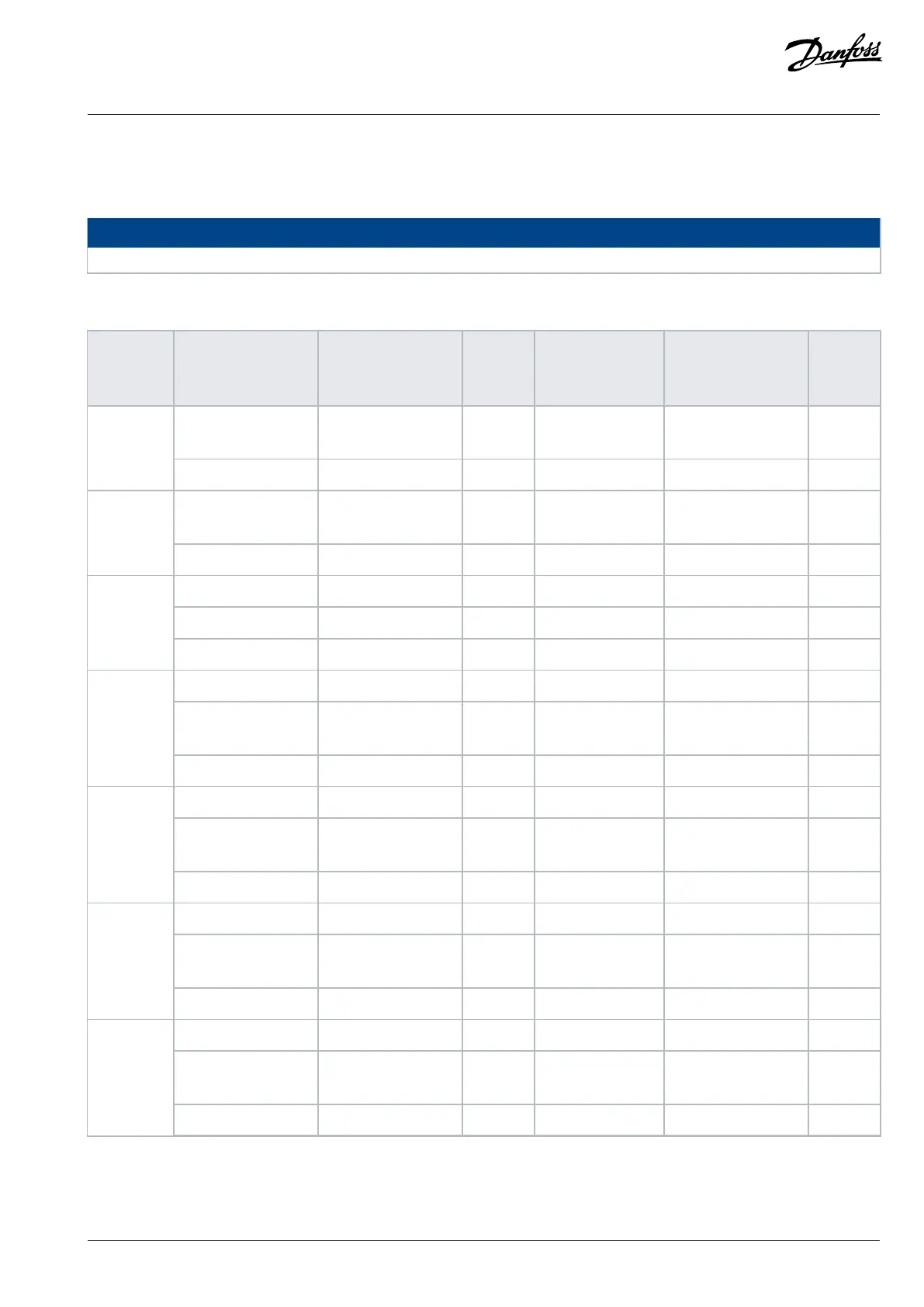
Table 33: Power Cable Sizing
Enclosure
size
Terminal
Cross-section [mm
2
(AWG)]
Torque
[Nm (lb-
in)]
Stripping length
[mm (in)]
Connector type Screw/
lug type
Mains, motor, and DC
connection
0.5–4.0 (24–10) 0.7 (6.2) 7–9 (0.28–0.35) Terminal block SlotMA01c
Customer relay 0.5–2.5 (24–12) 0.5 (4.4) 6–7 (0.24–0.28) Terminal block Slot
Mains, motor, and DC
connection
0.5–4.0 (24–10) 0.7 (6.2) 7–9 (0.28–0.35) Terminal block SlotMA02c
Customer relay 0.5–2.5 (24–12) 0.5 (4.4) 6–7 (0.24–0.28) Terminal block Slot
Mains and motor 0.5–4.0 (24–10) 0.7 (6.2) 7–9 (0.28–0.35) Terminal block Slot
DC connection 2.1–5.3 (14–10) – 6–7 (0.24–0.28) Straight receptacles –
MA01a
Customer relay 0.5–2.5 (24–12) 0.5 (4.4) 6–7 (0.24–0.28) Terminal block Slot
Mains and motor 0.5–4.0 (24–10) 0.7 (6.2) 7–9 (0.28–0.35) Terminal block Slot
Brake
(1)
and DC con-
nection
2.1–5.3 (14–10) – 6–7 (0.24–0.28) Straight receptacles –
MA02a
Customer relay 0.5–2.5 (24–12) 0.5 (4.4) 6–7 (0.24–0.28) Terminal block Slot
Mains and motor 0.5–4.0 (24–10) 0.7 (6.2) 7–9 (0.28–0.35) Terminal block Slot
Brake and DC con-
nection
2.1–5.3 (14–10) – 6–7 (0.24–0.28) Straight receptacles –
MA03a
Customer relay 0.5–2.5 (24–12) 0.5 (4.4) 6–7 (0.24–0.28) Terminal block Slot
Mains 0.5–16 (22–6) 1.2 (10.6) 12–13 (0.47–0.51) Terminal block Slot
Motor, brake, and DC
connection
0.5–16 (20–6) 1.2 (10.6) 12–15 (0.47–0.59) Terminal block Slot
MA04a
Customer relay 0.5–2.5 (24–12) 0.5 (4.4) 6–7 (0.24–0.28) Terminal block Slot
Mains 0.5–16 (22–6) 1.2 (10.6) 12–13 (0.47–0.51) Terminal block Slot
Motor, brake, and DC
connection
0.5–16 (20–6) 1.2 (10.6) 12–15 (0.47–0.59) Terminal block Slot
MA05a
Customer relay 0.5–2.5 (24–12) 0.5 (4.4) 6–7 (0.24–0.28) Terminal block Slot
1) For MA02a, only 3x200–240V and 3x380–480V drives have brake function.
Danfoss A/S © 2024.08 AJ402315027937en-000401 / 130R1239 | 47