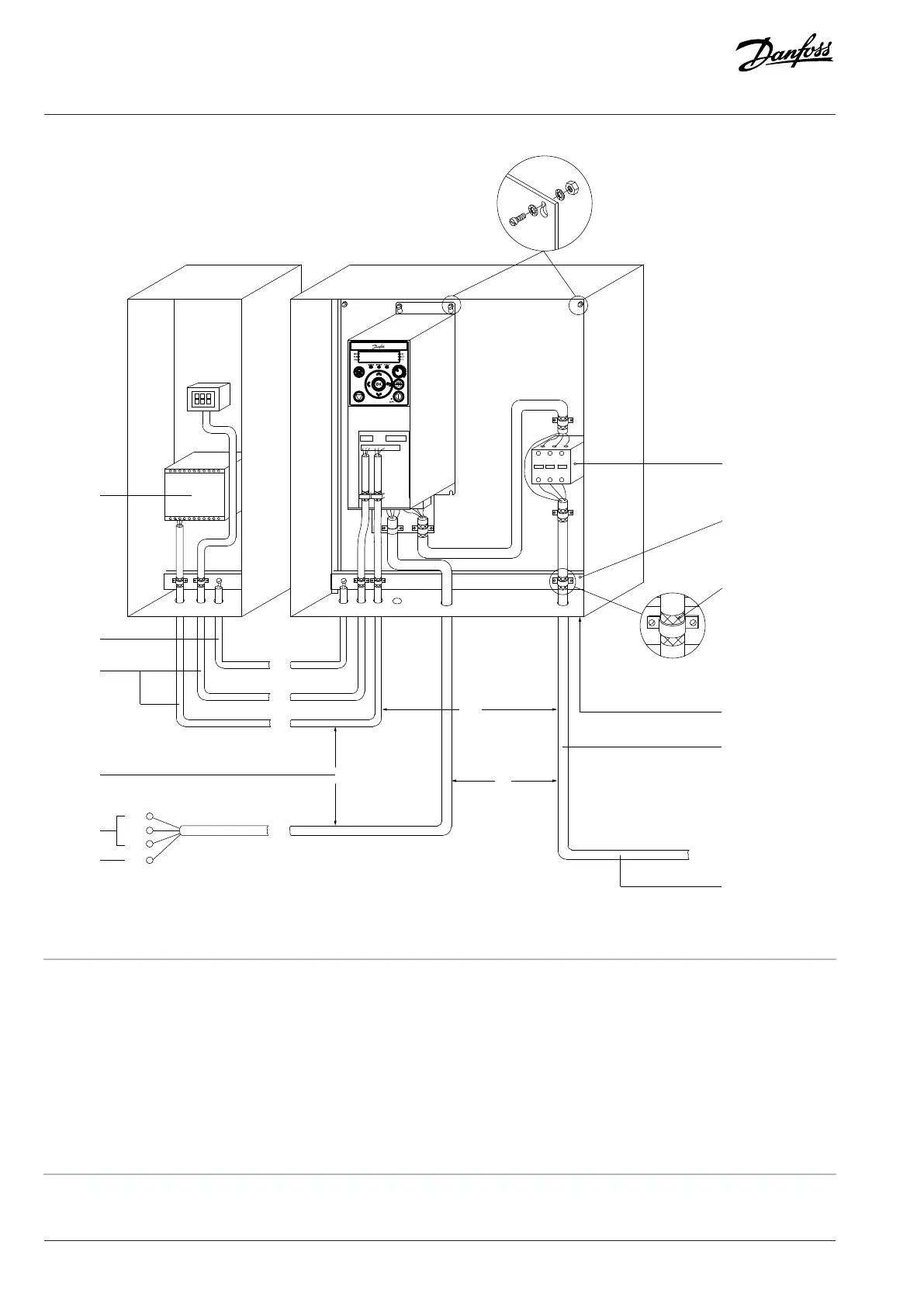
Figure 39: Example of Proper EMC Installation
1 Programmable logic controller (PLC) 2
Minimum 16mm
2
(6AWG) equalizing cable
3 Control cables 4 Minimum 200mm (7.9in) between control cables, motor
cables, and mains cables
5 Mains supply 6 Reinforced protective earth
7 Output contactor, and so on. 8 Grounding rail
9 Cable insulation stripped 10 All cable entries in one side of panel
11 Motor cable 12 Connecting to motor (3 phases and protective earth)
80 | Danfoss A/S © 2024.08 AJ402315027937en-000401 / 130R1239
Design Guide | iC2-Micro Frequency Converters Electrical Installation Considerations