2 = "No Action", F20 not activated
Selects the control board firmware response to safety function status
changes.
0 = "Default", F46/F47/F48 activated as alarm (application may de-
crease the reporting level, e.g. warning -> no action)
1 = "Violat only", F48 activated as alarm, F46/F47 not activated
2 = "No Action", F46/F47/F48 not activated
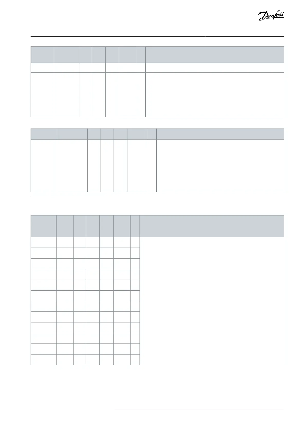
Table 20: Encoder (G7.4.1.3)
Time used to calculate actual speed value. Note: Use value 1 in
closed loop mode.
0 = No
1 = 1 ms
2 = 5 ms
3 = 10 ms
4 = 50 ms
1
The menu group is accessible only when the Advanced safety option board is installed in slot C.
Table 21: Safety Functions Group (G7.4.2.1)
Shows the status of the safety function.
Not in use = The function is not taken into use in the parameter file.
Inactive = The safety function is not requested.
Requested = The safety function is requested.
Active = The safety function is active. (The signal xxx Active is "1".)
Reached = The safety function is reached. (The signal xxx Reached is "1".)
AQ319736045637en-000101 / DPD01798 | 47Danfoss A/S © 2021.06
Overview of the System
VACON® NXP Advanced Safety Options
Operating Guide