DIMENSIONING SETUP AND CALIBRATION
6. Enter a width of the side margins used to create transition on the outer edge of the
scanning area. (see section 4.6.2).
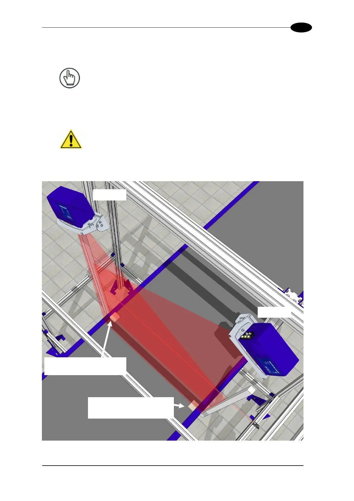
Figure 56: Spacer placement
NOTE: Side margins of equal width are used to create transitions on
the scan line when there are no side rails or edge transitions.
If the spacers are placed inside the belt width, the spacer width must
be entered into the Side Margins text field. If the spacers are placed
outside the edge of the belt, or if side rails are present, a "0" must be
entered into the Side Margins text field for the spacer width.
IMPORTANT: Only one side margin is placed in the laser beam for
each DM3610. One in the laser beam of HEAD1 at the far edge of the
conveyor, and one for HEAD2 at the far edge of the conveyor, as
shown in the illustrations below. Each side margin should only intersect
one laser.
Side Margins for HEAD 1
(Outside)
Side Margins for HEAD 2
(Inside)


 To Next Page