Product Reference Guide 3
nect the female to the male end from the keyboard and the remaining end at
the keyboard port at the terminal/PC. Reference Figure 1a.
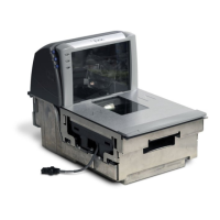
Figure 2. Features and Labeling
6
5
1
9
7
8
13
12
11
10
2
3
4
1
Back Cover
8
P/N Label
2
Scanner Push Button
9
USB/SD Cover
3
Camera Push Button
10
USB Service Port — On Screen Pro-
gramming Tool
4
Scan Window
11
microSD Card Slot — Upgrade, imag-
ing, statistics data
5
Cable Connector Cover
12
Host (blue) Port — POS terminal, label
data, application host download, host
commands to scanner
6
Checkpoint EAS Wire Cav-
ity Electrical Article Sur-
veillance Antenna
Connection
13
Auxiliary (yellow) Port for RS-232
handheld scanner, EAS Interlock, PIR
data, etc.
7
Serial Number/Regula-
tory Label

 Loading...