6 Magellan™ 3200VSI
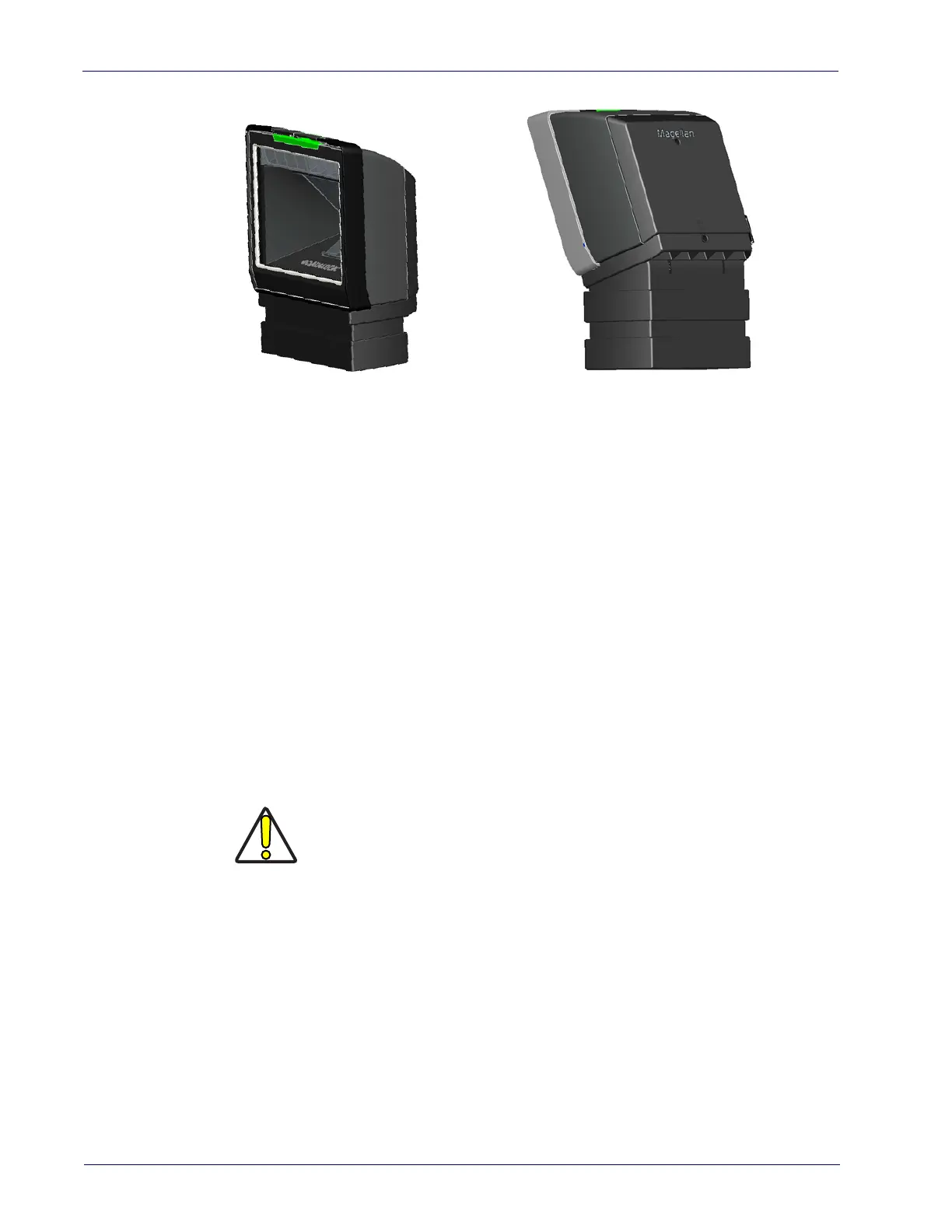
Figure 4. Using the Risers
One Riser
Two Risers stacked. Scan-
ner and L-Bracket have
been tilted on the top Riser.
ab
Wall Mount
Attach the L-Bracket to the wall, securing it in the desired position with two
screws through the two holes in the back face of the L-Bracket as shown in Fig-
ure 3. Recommendation: Use two Pan Head (8.2mm or 5/16” maximum head
diameter) #8 screw with a thread profile that suits the mounting surface mate-
rial in the wall.
Countertop Mount
If using the L-Bracket alone for countertop installation, secure the bracket in
place using two screws through the bottom face of the bracket (see Figure 3). If
risers are used, secure a riser to the countertop by attaching two screws
thro
ugh its screw holes. Recommendation: Use two Pan Head (8.2mm or 5/16”
maximum head diameter) #8 screw with a thread profile that suits the mount-
ing surface material in the countertop.
CAUTION
Do not use a countersink type of screw head. Damage
will occur from use of a countersunk screw head in the
plastic screw bosses
Risers may be stacked as shown in Figure 4b. Each riser increments the height
of the mounted scanner by 1.5” (38.1mm). Ri
ser pieces readily snap together or
apart and allow for adjustable tilt of the scanner/L-Bracket of up to 20 degrees
in 5° increments. Figure 4b provides an example of a tilted scanner.

 Loading...