Chapter 6 Description of Operations
PAGE 6-46
(2) Options
SYS.030 Setting Change Unlock Code Standard setting: 000000
Restrict the setting so that it can not be changed directly from the controller.
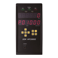
When a value other than the standard setting is set, changing the controller to the PROGRAM mode
displays the numeric value input screen.
By entering the value set in SYS.030 to the numeric value input screen, Controller shifts to set
value selection mode.
Also, there is no restriction on external setting changes such as user console.
SYS.033 System Option 1 Standard setting: 000000
Optional functions of the Unit are set here.
*****1: Accept Relay output (0: continuous /1:pulse)
・Set to “1” if the QL-OK output signal of the standard IO is to be in pulse form.
****1*: Total Accept Relay Output (0: continuous /1:pulse)
・Set to “1” if the TOTAL-OK output signal of the standard IO is to be in pulse form.
***1**: Accept Relay Output Timing(0:300msec/1:800msec)
・If the pulse method has been selected, select the pulse length here.
**1***: Stop input (0: Open Stop/1: Close Stop)
・Set to “1” if the logic of the STOP input signal is to be set to the B contact.
*1****: Self check (0: Startup Time /1: Only the first cycle)
・Set to "1" to perform the CAL check at the fastening start only in the first cycle.
Except when a judgment other than the one of the ACCEPT Spindle is made in the first cycle,
the CAL check is performed at the next fastening start, too.
1*****: ID Data input select (0:Fieldbus/1:Expansion RS232C)
・For selecting whether the ID data are to be input as a fieldbus message or input in the RS232C-2
port.
SYS.034 System Option 2 Standard setting: 000000
Optional functions of the Unit are set here.
*****1: WORK change (0: Display panel/1: PLC I/O Signal)
・Set to “1” if the change of WORK is to be performed from the external I/O (the change cannot be
performed from both the operation panel and the external I/O)
****1*: CW/CCW switch (0: Slide/1: Push Button)
· 0: P type, T type, Ltype, Dtype
· 1: A type, S type
***1**: RS232C-1 output (0: PLC/1: Ethernet)
· 0: PLC outputs in FUSION compatible format.
· 1: When using ETHERNET board, set here.
**1***: NG result indication (0: enable/1: disable)
・Set to “1” if the NG result indication is not to be performed.
*1****: Fieldbus Function Disable (0:OFF / 1: ON)
・Set to “1” if Fieldbus is to be disabled with Fieldbus being installed.
1*****: WORK change priority (0: Fieldbus/1: standard I/O)
・For selecting between using Fieldbus or the standard I/O when the change of WORK is to be
performed by the external I/O.
S0140185-H
 Loading...