Chapter 4 Installation
PAGE 4-16
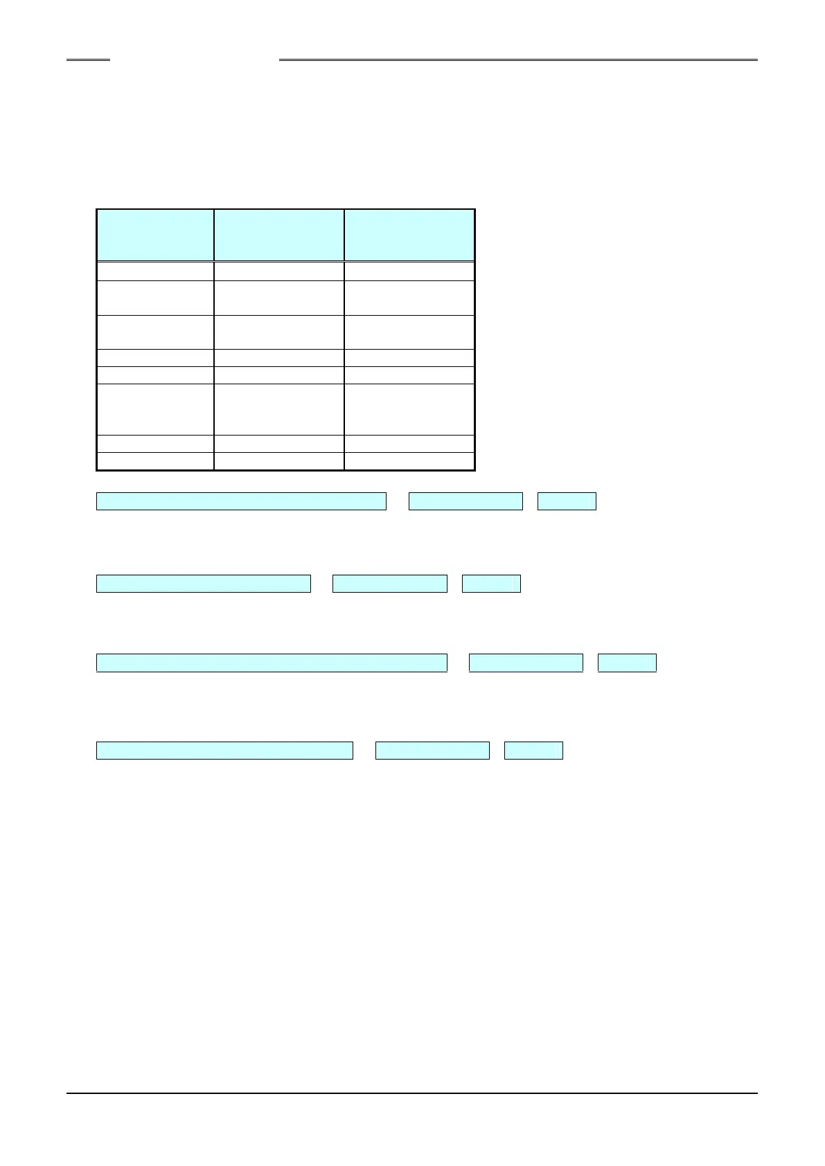
(2) Output Signals
When an output signal is “ON,” the voltage at the corresponding output terminal is at the same level
as the output common voltage (0V).
Depending on the output status of the BANK SELECT signal, the output content of some output pins
changes.
ON: Connected to 0V.
OFF:Same as the input common (HIGH)
level or is open.
FASTENING
RESULT
DATA AVAILABLE
NG: FASTENING NG (FAILURE) SIGNAL PIN No.: TB2-1 OUT-1
The “ON” output is performed when an abnormal exit occurs with a fastening result falling outside a
judgment range.
OK: FASTENING OK SIGNAL PIN No.: TB2-2 OUT-2
The “ON” output is performed when normal exit is accomplished with the fastening results being
within the judgment ranges.
ABNORMAL: SYSTEM ERROR/ABNORMAL EXIT PIN No.: TB2-3 OUT-3
The “ON” output is performed when an error is detected during the system check performed by the
Unit or during the fastening process.
When an error occurs, fastening is stopped immediately and the fastening results data are stored.
READY: INPUT ENABLING SIGNAL PIN No.: TB2-4 OUT-4
The “ON” output is performed when operation fastening, reverse rotation, etc., can be performed by
an input signal from the PLC or other external equipment.
The READY signal is “OFF” under the following conditions.
◎During the initialization process in power activation
◎During reverse rotation
◎When the ABNORMAL signal is output
◎In the BYPASS mode (during settings, in the download mode (during communication), etc.)
◎In the STOP state
◎During fastening, reset, or CAL check
◎Other conditions where operation of the Unit by an external output is disabled
S0140185-H