b Tighten the second screw completely.
c Return to the rst screw and tighten it completely.
If the PHM slips o the blue retention clips when the screws are partially tightened, follow these steps to secure the PHM:
a Loosen both the heat sink screws completely.
b Lower the PHM on to the blue retention clips, follow the procedure described in step 2.
c Secure the PHM to the system board, follow the procedure described in step 4.
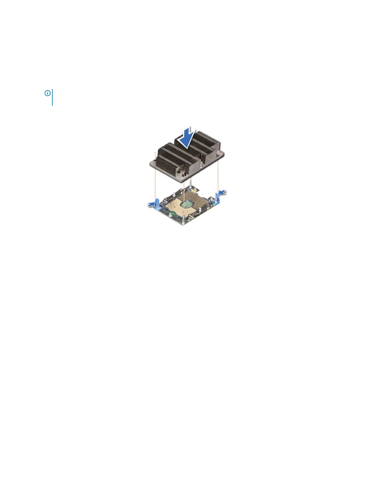
NOTE: The processor and heat sink module retention screws should not be tightened to more than 0.13 kgf-m (1.35 N.m
or 12 in-lbf).
Figure 43. Installing a processor and heat sink module (1U)
Next step
Follow the procedure listed in After working inside your system.
System memory
Removing a memory module
Prerequisites
1 Follow the safety guidelines listed in Safety instructions.
2 Follow the procedure listed in Before working inside your system.
3 Remove the following:
a Remove the system cover.
b Removing the air shroud.
Steps
1 Locate the DIMM sockets. Push the ejectors outward on both ends of the memory module socket to release the memory module from
the socket.
2 Holding the DIMM by the edges, lift it from the socket, and store it in an anti-static package.
Installing and removing system components
67