Figure 102. Installing the right ear handle for Rear Accessed configuration
Next steps
1. Install the expansion card riser 1.
2. Install the air shrouds.
3. Follow the procedure listed in the After working inside your system.
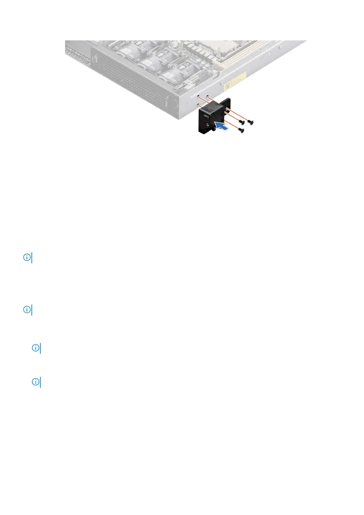
Removing the status LED control panel for Front Accessed
configuration
Prerequisites
NOTE: For Front Accessed configuration, the status LED control panel is on the rear of the system.
1. Follow the safety guidelines listed in the Safety instructions.
2. Follow the procedure listed in the Before working inside your system.
3. Remove the air shrouds.
4. Remove the processor and heat sink module.
5. Remove the expansion card riser 1.
NOTE: If required, remove the backplane power and signal cables.
Steps
1. Disconnect the status LED control panel cable from the system board connector.
NOTE: Observe the routing of the cable as you remove it from the system.
2. Using the Torx #8 screwdriver, remove the screws that secure the status LED control panel assembly to the system.
3. Hold the left status LED control panel assembly and remove the control panel along with the cable from the system.
NOTE: The numbers on the image do not depict the exact steps. The numbers are for representation of sequence.
102 Installing and removing system components

 Loading...


