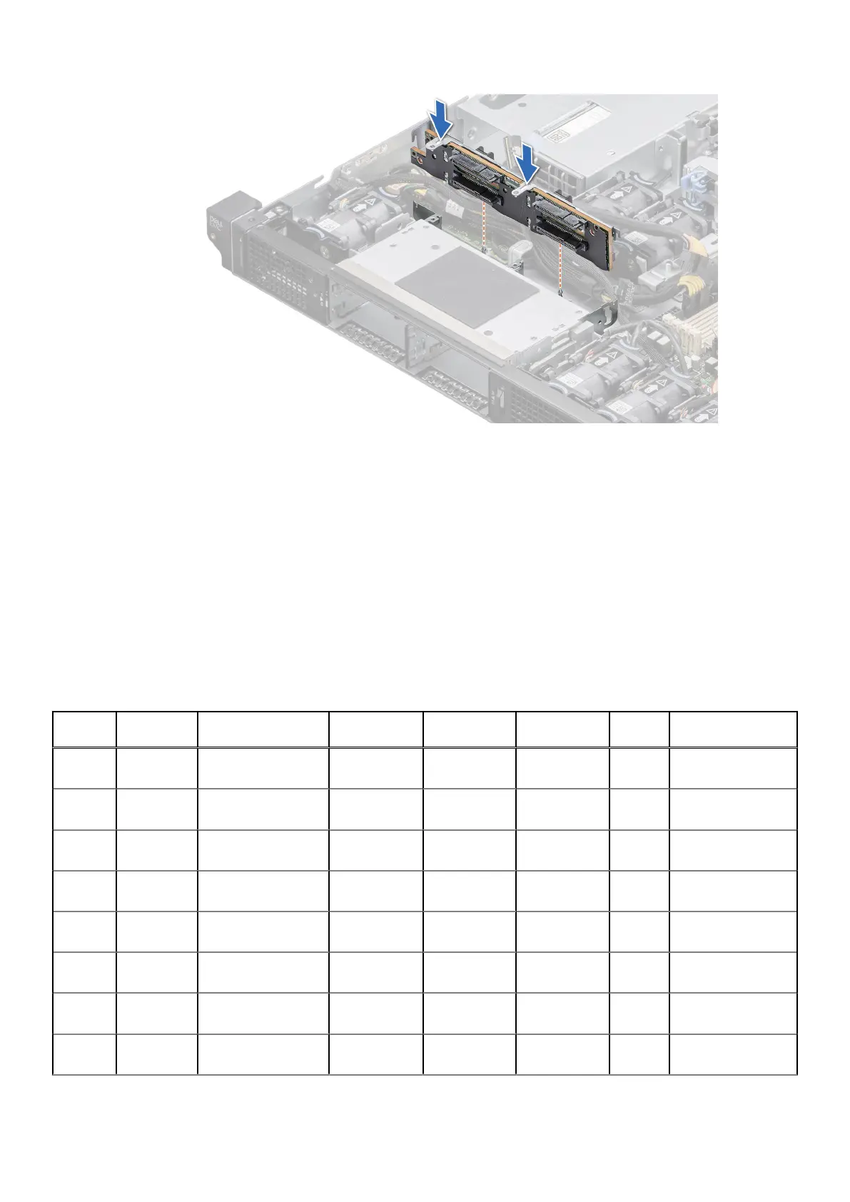
Figure 38. Installing the drive backplane
Next steps
1. Connect the cables to the backplane and then verify that both power and signal cable connections are fully seated to the
backplane and system board.
2. Install all the drives.
3. Install the PCI air shroud.
4. Follow the procedure listed in After working inside your system.
Internal storage configuration matrix for XR11
Table 14. Internal storage configuration matrix
Configu
ration
Chassis
orientation
Base configuration
description
Backplane
description
Storage
controller(s)
Controller
form factor
BOSS
enabled
Riser
configuration
1 Front
Accessed
ASSY, CHAS, RAF,
4HD, 3PCI, 1U, XR11
4 x 2.5-inch
NVMe (only)
H755 Adapter Y C0/1: R1B+R2+R3
2 Front
Accessed
ASSY, CHAS, RAF,
4HD, 3PCI, 1U, XR11
4 x 2.5-inch
NVMe (only)
S150 Direct Attach
(SL)
Y C0/1: R1B+R2+R3
3 Front
Accessed
ASSY, CHAS, RAF,
4HD, 3PCI, 1U, XR11
4 x 2.5-inch
SAS/SATA
H345 Adapter Y C0/1: R1B+R2+R3
4 Front
Accessed
ASSY, CHAS, RAF,
4HD, 3PCI, 1U, XR11
4 x 2.5-inch
SAS/SATA
H755 Adapter Y C0/1: R1B+R2+R3
5 Front
Accessed
ASSY, CHAS, RAF,
4HD, 3PCI, 1U, XR11
4 x 2.5-inch
SAS/SATA
HBA355i Adapter Y C0/1: R1B+R2+R3
6 Front
Accessed
ASSY, CHAS, RAF,
4HD, 3PCI, 1U, XR11
4 x 2.5-inch
SATA (only)
Onboard
SATA
Onboard
SATA
Y
C0/1: R1B+R2+R3
7 Rear
Accessed
ASSY, CHAS, NAF,
4HD, 3PCI, 1U, XR11
4 x 2.5-inch
NVMe (only)
H755 Adapter Y C0/1: R1B+R2+R3
8 Rear
Accessed
ASSY, CHAS, NAF,
4HD, 3PCI, 1U, XR11
4 x 2.5-inch
NVMe (only)
S150 Direct attach
(SL)
Y C0/1: R1B+R2+R3
Installing and removing system components 49

 Loading...


