2. Route the cable properly to prevent the cable from being pinched or crimped.
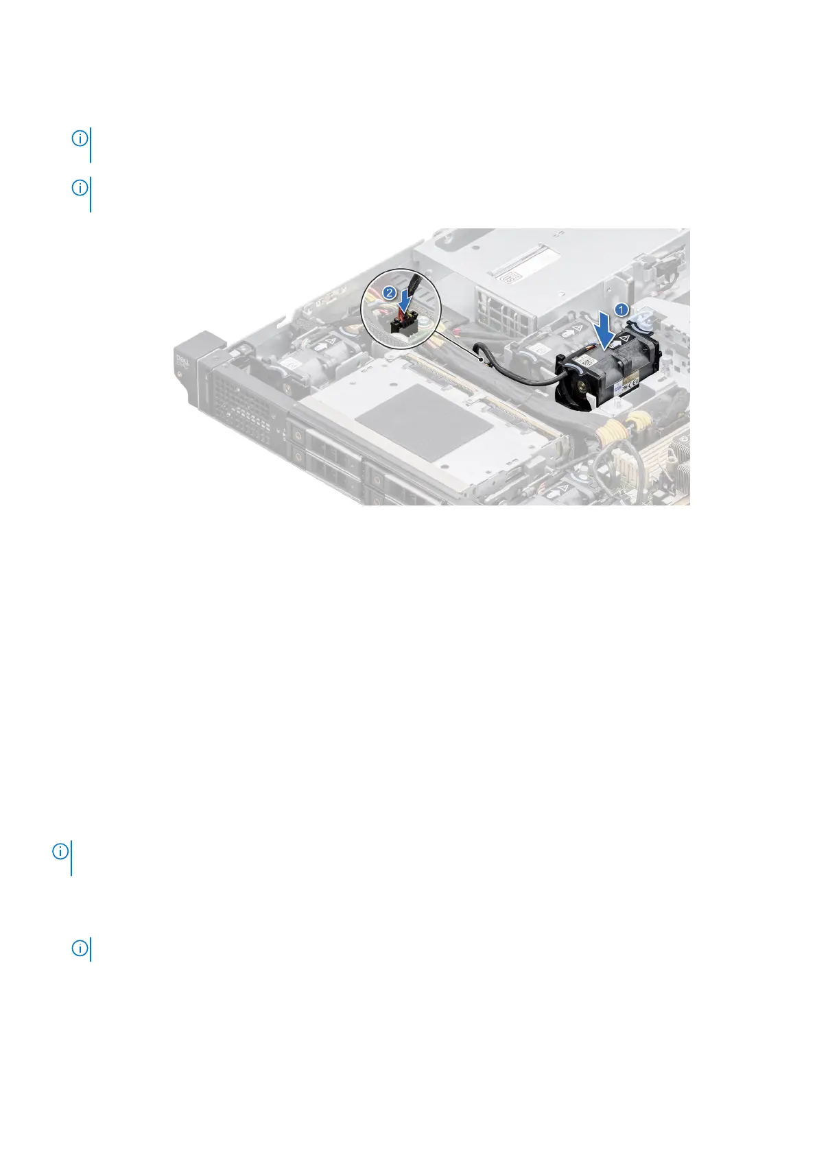
3. Press the release tabs on the fan cable connector and connect the cable to the system board.
NOTE: Ensure to connect the fan cable to the correct fan connector on the system board. Check the SIL label for
correct fan header location.
NOTE: To install Fan 5 and 6, remove the processor and heat sink module. After installing the fans replace the
processor and heat sink module for system with extended heat sink module.
Figure 27. Installing a cooling fan
Next steps
1. If removed, install the air shrouds.
2. Follow the procedure listed in After working inside your system.
Intrusion switch module
This is a service technician replaceable part only.
Removing the intrusion switch module
Prerequisites
1. Follow the safety guidelines listed in the Safety instructions.
2. Follow the procedure listed in the Before working inside your system.
NOTE:
The procedure to remove the intrusion switch module is the same for Rear Accessed and Front Accessed
configurations.
Steps
1. Disconnect and remove the intrusion switch cable from the connector on the power interposer board (PIB).
NOTE: Observe the routing of the cable as you remove it from the system.
2. Using the Phillips #1 screwdriver, remove the screw securing the intrusion switch module.
3. Lift the intrusion switch module out of the system.
Installing and removing system components
39

 Loading...


