Expansion card installation guidelines
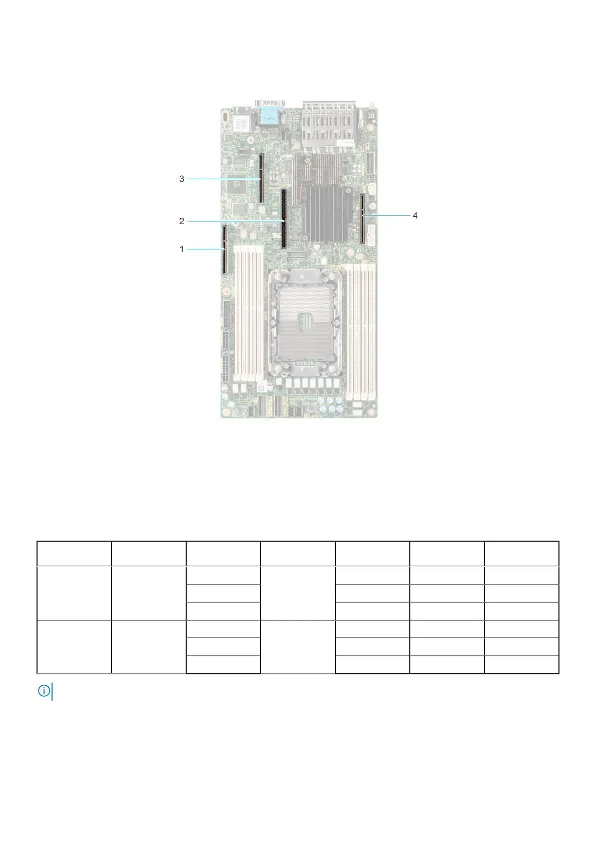
Figure 58. Expansion card slot connectors
1. IO_Riser3 ( Riser 3 connector)
2. BOSS S1 card connector
3. IO_Riser2 ( Riser 2 connector)
4. IO_Riser1 (Riser 1 connector)
The following table describes the expansion card riser configurations:
Table 25. Expansion card riser configurations
Configurations Expansion card
risers
PCIe Slots Controlling
processor
Height Length Slot width
Config0. R1B+R2+R3
Rear Accessed
configuration
1 Processor 1 Low profile Half length x8
2 Full Height Half length x16
3 Full Height Half length x16
Config1. R1B+R2+R3
Front Accessed
configuration
1 Processor 1 Low profile Half length x8
2 Low profile Half length x16
3 Full Height Half length x16
NOTE: Riser 2 and 3 are combined in one expansion card riser module.
68 Installing and removing system components

 Loading...


