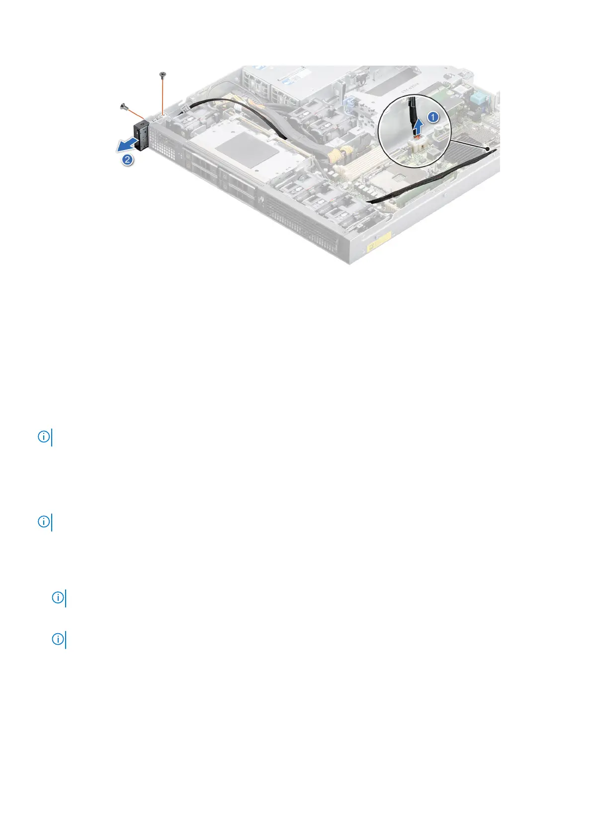
Figure 103. Removing the status LED control panel for Front Accessed configuration
Next steps
Replace the status LED control panel for Front Accessed configuration.
Installing the status LED control panel for Front Accessed
configuration
Prerequisites
NOTE: For Front Accessed configuration, the status LED control panel is on the rear of the system.
1. Follow the safety guidelines listed in the Safety instructions.
2. Follow the procedure listed in the Before working inside your system.
3. Remove the air shrouds.
4. Remove the processor heat sink module.
5. Remove the expansion card riser 1.
NOTE: If required, remove the backplane power and signal cables.
Steps
1. Align and insert the status LED control panel assembly in the slot on the system.
2. Route the status LED control panel cable through the guide slots in the system and connector on system board.
NOTE: Route the cable properly to prevent the cable from being pinched or crimped.
3. Using the Phillips #1 screwdriver, tighten the screws that secure the status LED control panel assembly to the system.
NOTE: The numbers on the image do not depict the exact steps. The numbers are for representation of sequence.
Installing and removing system components 103

 Loading...


