Table 14. Internal storage configuration matrix (continued)
Configu
ration
Chassis
orientation
Base configuration
description
Backplane
description
Storage
controller(s)
Controller
form factor
BOSS
enabled
Riser
configuration
9 Rear
Accessed
ASSY, CHAS, NAF,
4HD, 3PCI, 1U, XR11
4 x 2.5-inch
SAS/SATA
H345 Adapter Y C0/1: R1B+R2+R3
10 Rear
Accessed
ASSY, CHAS, NAF,
4HD, 3PCI, 1U, XR11
4 x 2.5-inch
SAS/SATA
H755 Adapter Y C0/1: R1B+R2+R3
11 Rear
Accessed
ASSY, CHAS, NAF,
4HD, 3PCI, 1U, XR11
4 x 2.5-inch
SAS/SATA
HBA355i Adapter Y C0/1: R1B+R2+R3
12 Rear
Accessed
ASSY, CHAS, NAF,
4HD, 3PCI, 1U, XR11
4 x 2.5-inch
SATA (only)
Onboard
SATA
Onboard
SATA
Y C0/1: R1B+R2+R3
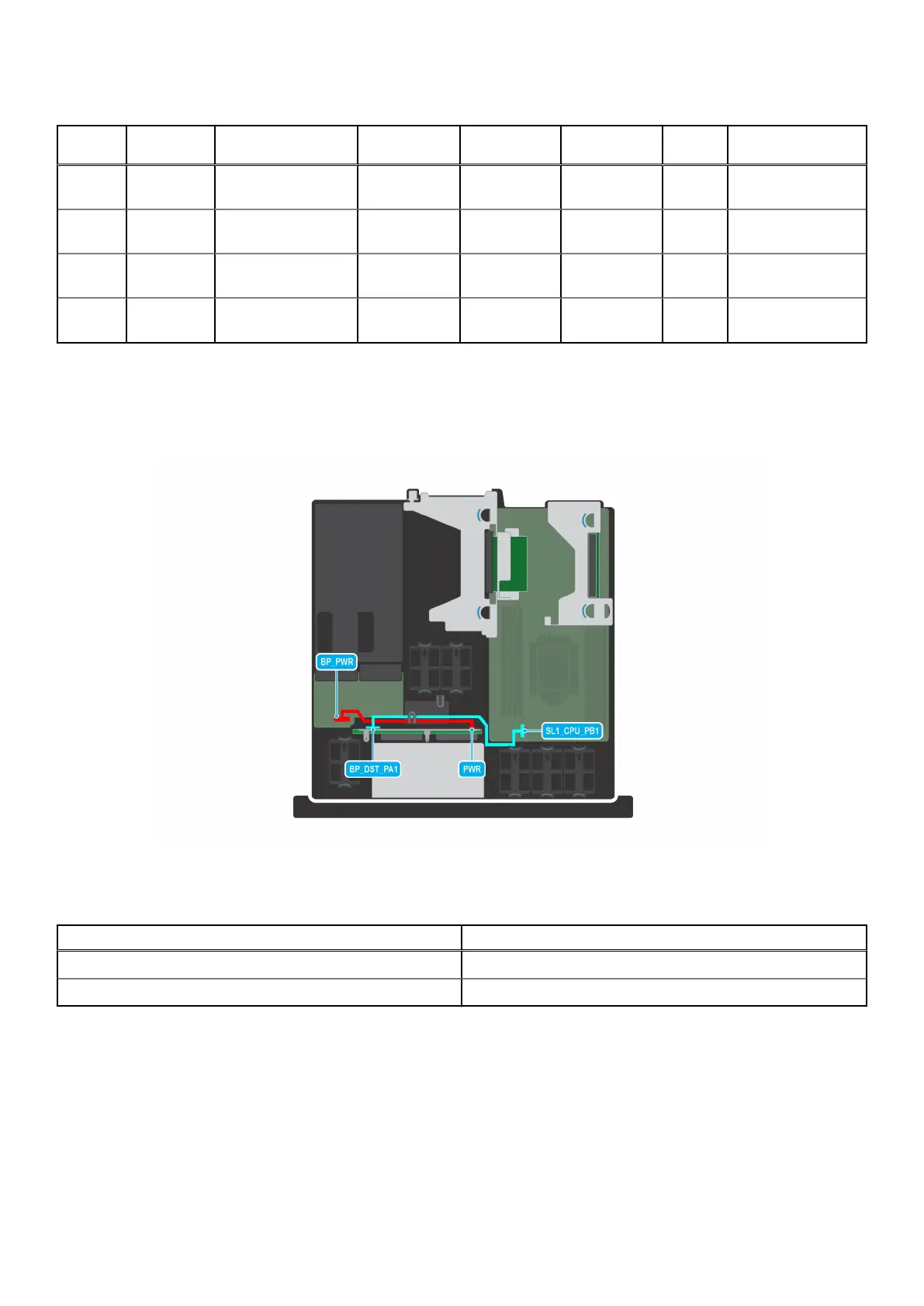
For cable routing information on the different configurations, please refer to the cable routing topic.
Cable routing
Figure 39. Cable routing - SL1 NVMe cable from system board to 4 x 2.5-inch drive backplane
Table 15. SL1 NVMe cable from system board to 4 x 2.5-inch drive backplane
From To
BP_PWR (Power connector on PIB) PWR (Power connector on backplane)
SL1_CPU_PB1 (NVMe signal connector on system board) BP_DST_PA1 (NVMe signal connector on backplane)
50 Installing and removing system components

 Loading...


