4. Place the processor connector side down on the processor tray. Ensure pin 1 marks are aligned.
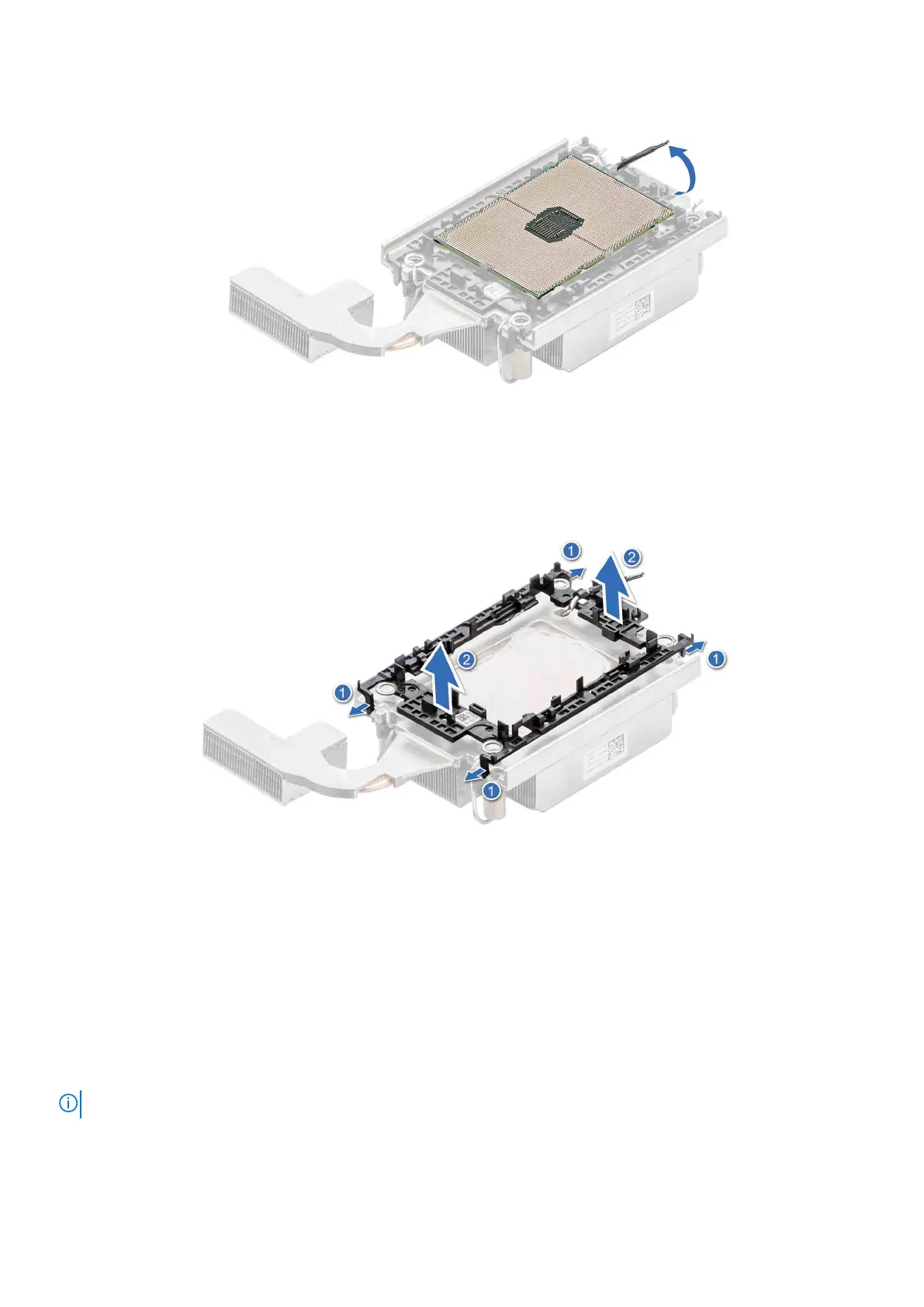
Figure 49. Lift up the TIM break lever
5. Using your thumb and index finger, first hold the carrier release tab at the pin 1 connector, pull out the tip of the carrier
release tab, and then lift the carrier partially from the heat sink.
6. Repeat the procedure at the remaining three corners of the carrier.
7. After all the corners are released from the heat sink, lift the carrier from the pin 1 corner of the heat sink.
Figure 50. Removing the processor carrier
Next steps
Replace the processor.
Installing the processor into a processor heat sink module
Prerequisites
1. Follow the safety guidelines listed in the Safety instructions.
2. Follow the procedure listed in Before working inside your system.
NOTE: The procedure to install the processor is the same for Rear Accessed and Front Accessed configurations.
Steps
1. Place the processor in the processor tray.
Installing and removing system components
61

 Loading...


