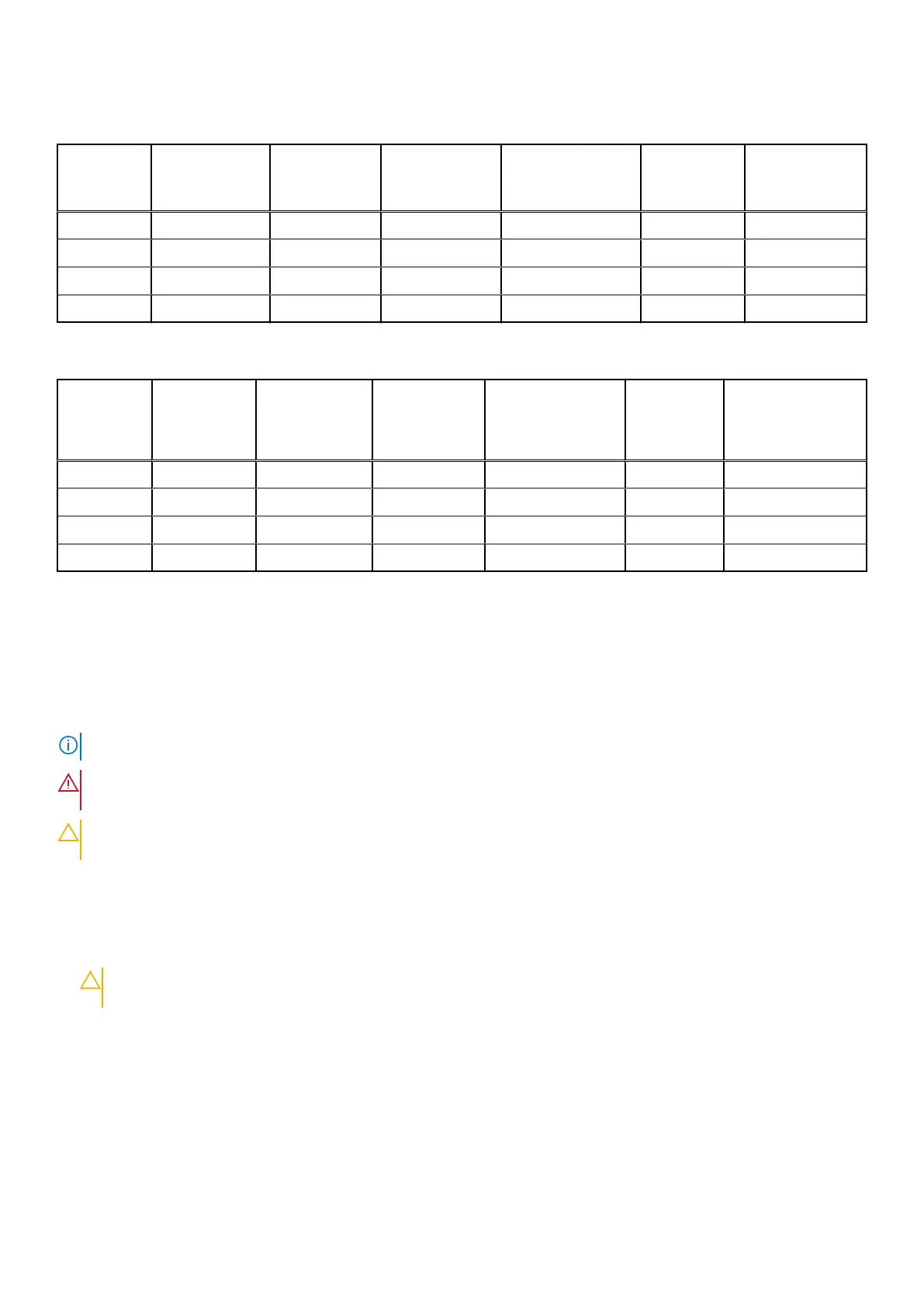
Table 23. Intel Optane PMem 200 Series Configuration 1 - 4 x RDIMMs/ LRDIMMs, 4 x Intel Optane PMem
200 Series
Total No of
RDIMMs/
LRDIMMs
Total No of
Intel Optane
PMem 200
Series DIMMs
1 R/LRDIMM
capacity (GB)
1 Intel Optane
PMem 200
Series capacity
(GB)
Total Standard
Memory Capacity
Total PM
Capacity
Supported
Modes
4 4 16 128 64 512 MM or AD
4 4 32 128 128 512 MM or AD
4 4 64 128 256 512 AD
4 4 128 128 512 512 AD
Table 24. Intel Optane PMem 200 Series Configuration 2 - 6 x RDIMMs/ LRDIMMs, 1 x Intel Optane
PMem 200 Series
Total No of
RDIMMs/
LRDIMMs
Total No of
Intel Optane
PMem 200
Series
DIMMs
1 R/LRDIMM
capacity (GB)
1 Intel Optane
PMem 200
Series
capacity (GB)
Total Standard
Memory Capacity
Total PM
Capacity
Supported Modes
6 1 16 128 96 128 AD
6 1 32 128 192 128 AD
6 1 64 128 384 128 AD
6 1 128 128 768 128 AD
Removing a memory module
Prerequisites
1. Follow the safety guidelines listed in the Safety instructions.
2. Follow the procedure listed in the Before working inside your system.
3. Remove the processor air shroud.
NOTE: The procedure to remove the memory module is the same for Rear Accessed and Front Accessed configurations.
WARNING: The memory modules are hot to touch for some time after the system has been powered off. Allow
the memory modules to cool before handling them.
CAUTION: To ensure proper system cooling, memory module blanks must be installed in any memory socket that
is not occupied. Remove memory module blanks only if you intend to install memory modules in those sockets.
Steps
1. Locate the appropriate memory module socket.
2. To release the memory module from the socket, simultaneously press the ejectors on both ends of the memory module
socket to fully open.
CAUTION:
Handle each memory module only by the card edges, ensuring not to touch the middle of the
memory module or metallic contacts.
3. Lift the memory module away from the system.
56
Installing and removing system components

 Loading...


