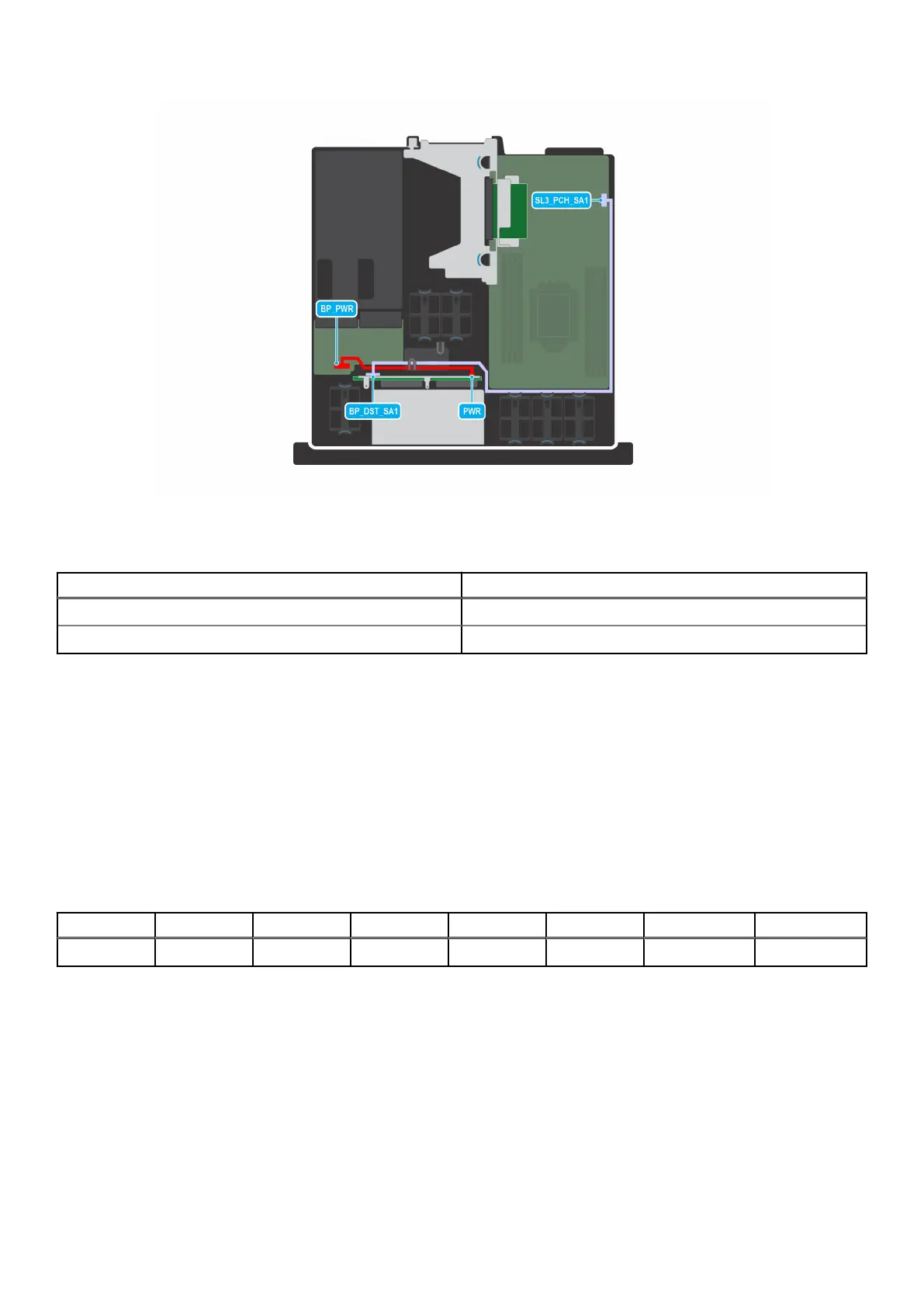
Figure 43. Cable routing- SATA cable from PERC to 4 x 2.5-inch drive backplane
Table 19. SATA cable from PERC to 4 x 2.5-inch drive backplane
From To
BP_PWR (Power connector on PIB) PWR (Power connector on backplane)
SL3_PCH_SA1 (SATA signal connector on system board) BP_DST_SA1 (SATA signal connector on backplane)
System memory
System memory guidelines
The PowerEdge XR11 system supports DDR4 registered DIMMs (RDIMMs), load reduced DIMMs (LRDIMMs) and Intel Optane
PMem 200 Series . System memory holds the instructions that are executed by the processor.
Your system contains 8 memory sockets organized into 8 channels to the processor.
Memory channels are organized as follows:
Table 20. Memory channels
Channel A Channel B Channel C Channel D Channel E Channel F Channel G Channel H
Slots A1 Slots A5 Slots A3 Slots A7 Slots A2 Slots A6 Slots A4 Slots A8
Installing and removing system components 53

 Loading...


