Figure 40. Cable routing - SL2 NVMe cable from system board to 4 x 2.5-inch drive backplane
Table 16. SL2 NVMe cable from system board to 4 x 2.5-inch drive backplane
From To
BP_PWR (Power connector on PIB) PWR (Power connector on backplane)
SL2_CPU_PA1 (NVMe signal connector on system board) BP_DST_PB1 (NVMe signal connector on backplane)
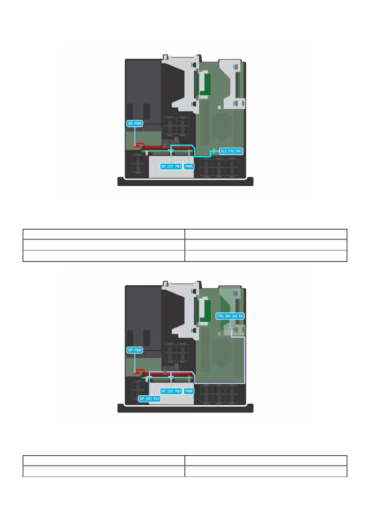
Figure 41. Cable routing- NVMe cable from PERC to 4 x 2.5-inch drive backplane
Table 17. NVMe cable from PERC to 4 x 2.5-inch drive backplane
From To
BP_PWR (Power connector on PIB) PWR (Power connector on backplane)
Installing and removing system components 51

 Loading...


