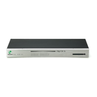
Hardware information LED indicators
Digi CM User Guide 180
LED indicators
Use the LED indicators to confirm your attachment to the network and that the Digi CM unit is able
to send and receive data.
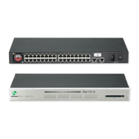
About serial port cabling
The Digi CM unit simplifies cabling. The RJ-45 8-pin configuration matches all SUN and Cisco RJ-45
console port configurations, enabling CAT 5 cabling without pinout concerns. Three DB-25 and one
DB-9 adapters come in the package. A DB-25 male, a DB-25 female, and a DB-9 adapter support
console management applications. A DB-25 male adapter provides a modem connection. See the
cable adapter information that follows later in this chapter.
Note The cable length restrictions common to RS-232 cables apply to the Digi CM serial cable as
well.
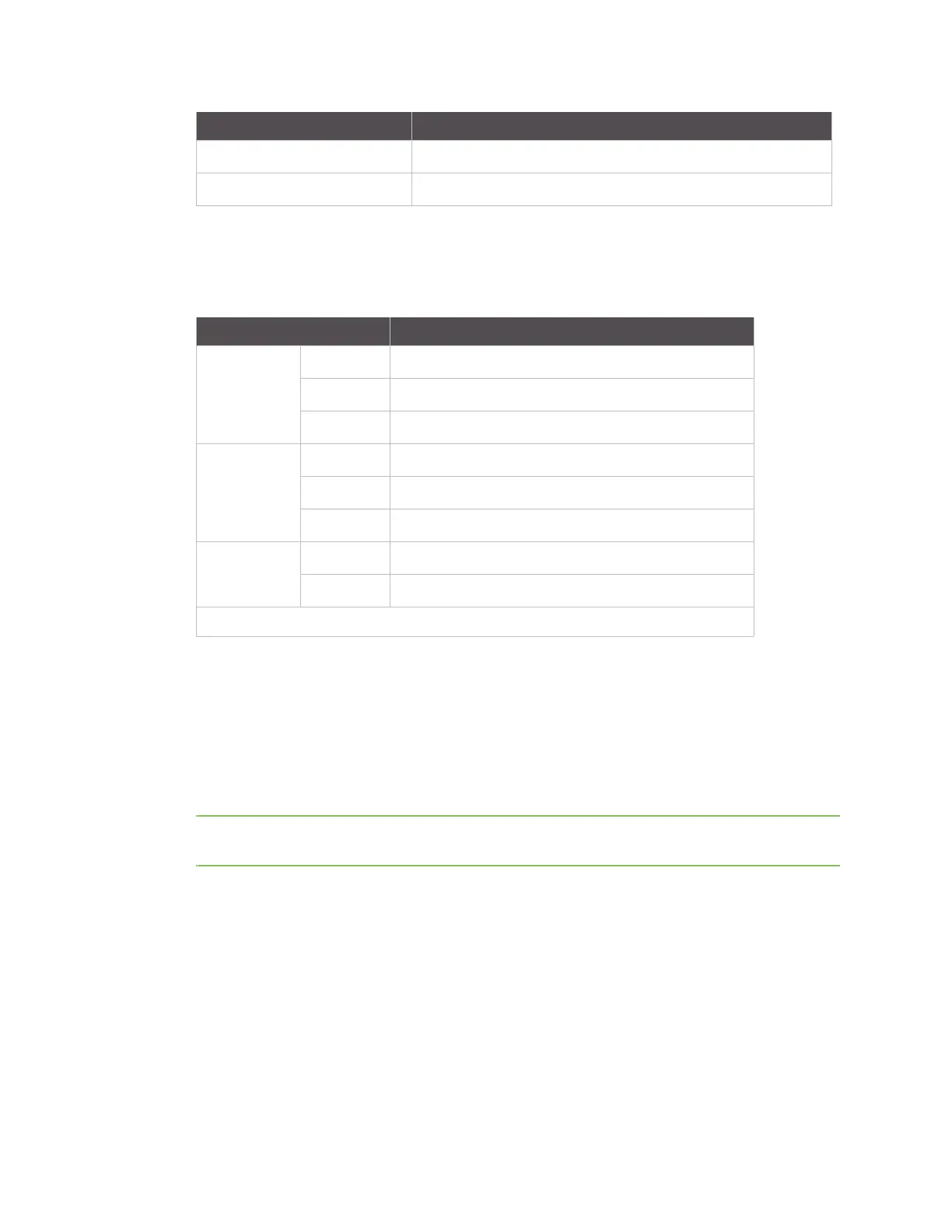
Dimensions 9.5” x 6.25” x 1.25” (241.3 cm 158.75 x 31.75 cm)
Weight 2.5 lbs (1.13 kilograms)
Attribute Value
LED Function
System Power On when power is supplied
Ready On when system is ready to run
PC On when a PC device is running
Ethernet 100Mbps On when 100Base-TX connection is detected
LINK On when connected to an Ethernet network
Act Blinks when there is activity on the Ethernet port
Serial port* In use On when the serial port is ready to run
Rx/Tx Blinks when there is traffic on the serial port
*Not available on the Digi CM 48