Monitor I/O lines
Pin configurations
Devices support both analog input and digital I/O line modes on several configurable pins.
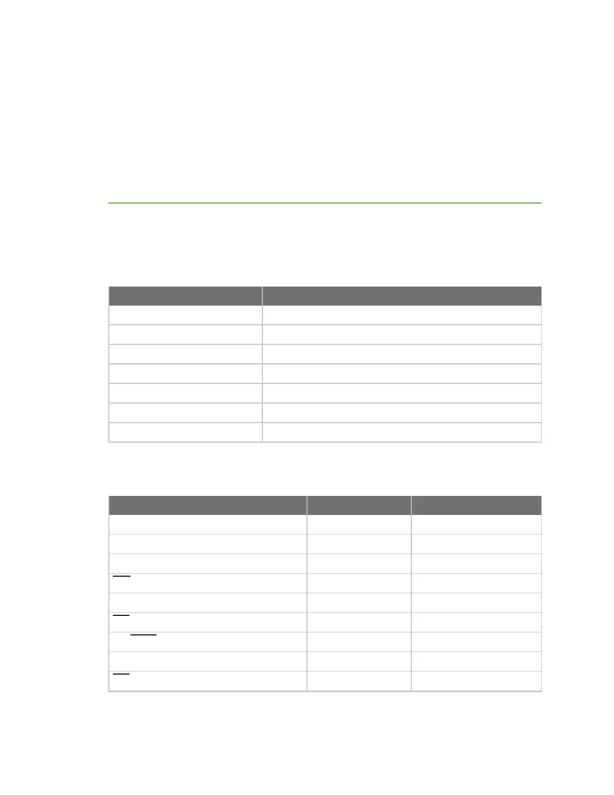
The following table provides typical parameters for the pin configuration commands (D0 - D9, P0 - P2).
Pin command parameter Description
0 Unmonitored digital input
(disabled)
1 Reserved for pin-specific alternate functionality
2 Analog input (A/D pins) or PWM output (PWM pins)
3 Digital input, monitored
4 Digital output, low
5 Digital output, high
6-9 Alternate functionality, where applicable
The following table provides the pin configurations when you set the configuration command for a
particular pin.
Device pin name Device pin number Configuration command
DIO12 5
P2
PWM0 / RSSI / DIO10 7
P0
PWM1 / DIO11 8
P1
DTR / SLEEP_RQ / DIO8
10
D8
DIO4 24
D4
CTS / DIO7
25
D7
ON/
SLEEP
/ DIO9 26
D9
ASSOC / AD5 / DIO5 15
D5
RTS / DIO6
29
D6
XBee®/XBee-PRO SX RF Module User Guide
164