Getting started with the XBee/XBee-PRO SX RF Module
Development Kit
Connect XBee-PRO SX development boards to
a PC
XBee®/XBee-PRO SX RF Module User Guide
25
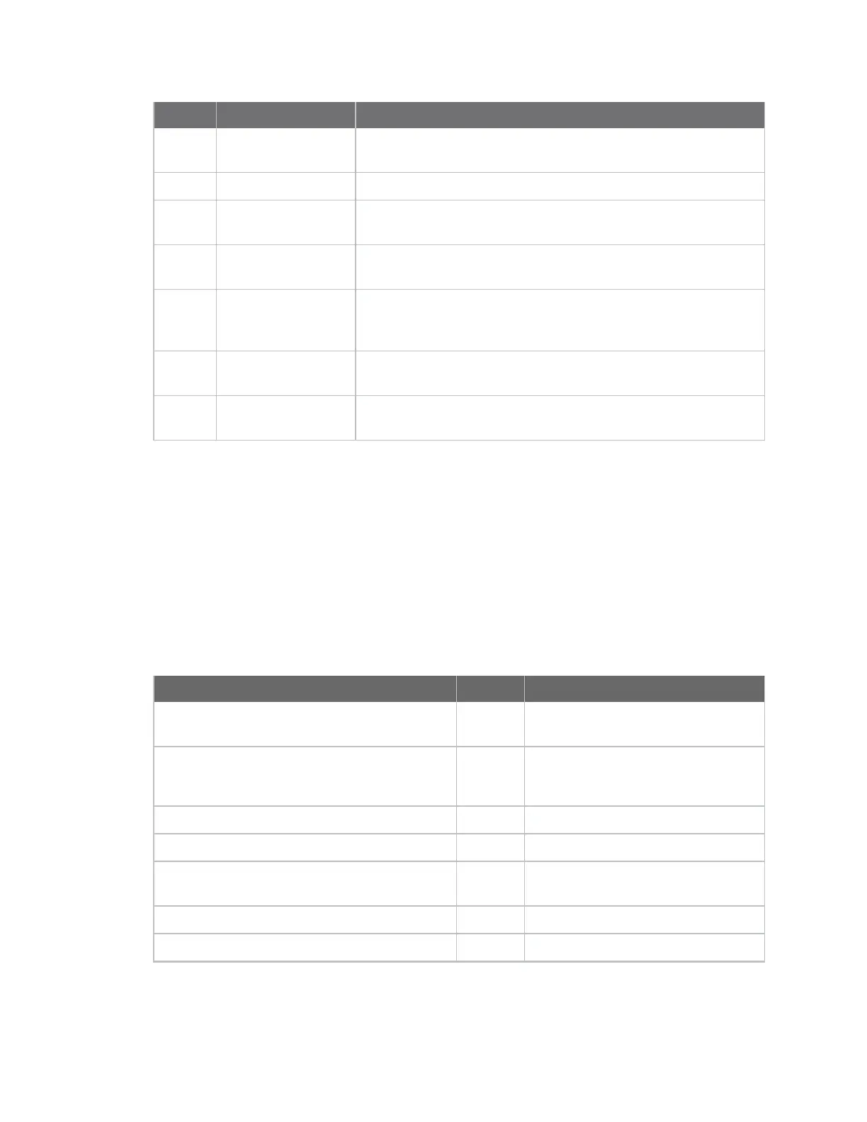
Number Item Description
5 Do not connect Do not connect to these pins. This development board does not
support the device's self power feature.
6 USB connector Connect a mini USB cable from this port to the host PC.
7 Reset button When pressed, the button switch resets the device by pulling pin 6
low.
8 Commissioning
button
When pressed, the button switch pulls the device's pin 33 low.
9 Development header 0.1” pitch header corresponds to pins 1 through 34 on the
XBee/XBee-PRO SX RF Module. Abbreviated labels are
silkscreened to the left of the header.
10 RPSMA connector Attach an antenna or RF cable to this jack. This connection is valid
only if the board has an RF pad XBee.
11
XBee/XBee-PRO SX
RF Modulefootprint
Connect XBee-PRO SX development boards to a PC
1. Connect both SX development boards to power supplies and plug the power supplies into an
outlet. The power supply is required when using the XBee-PRO SX because the current draw
when transmitting will exceed what a USB port can supply.
2. Connect the SX development boards to the USB port on a PC via the mini-USB cables. Separate
the SX development boards by at least 2 m (6 ft).
3. Connect the antennas to the RPSMA connector on the SX development boards.
The following table shows the XBee SX development kit contents.
Description Quantity Part number
XBee surface-mount (SMT) socket development
board
1 XBIB-U-SS
SX development board with onboard XBee-PRO
SXRF pad module
2
USA - XBIB-XBP9XR-0
Australia - XBIB-XBP9XR-2
Brazil - XBIB-XBP9XR-1
Standard USB cable 1 N/A
Mini USB cable 2 N/A
12 VDC power supply 2 Australia and Brazil include packages
of AC adapters
RPSMA antenna 3 A09-HASM-675
U.FL to RPSMA adapter cable 1 JF1R6-CR3-4I