Serial communication UART data flow
XBee®/XBee-PRO SX RF Module User Guide
59
UART data flow
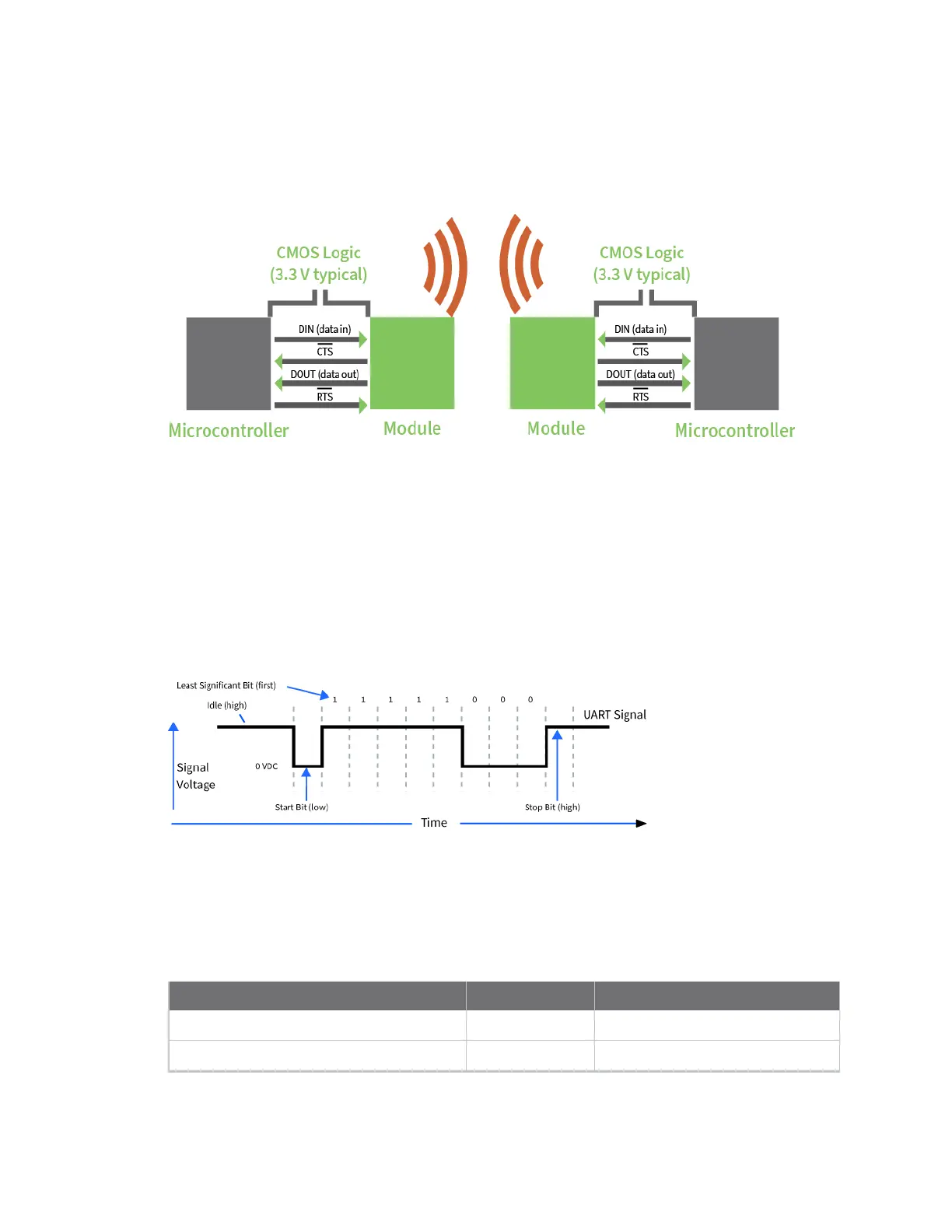
Devices that have a UART interface connect directly to the pins of the XBee/XBee-PRO SX RF Module
as shown in the following figure. The figure shows system data flow in a UART-interfaced
environment. Low-asserted signals have a horizontal line over the signal name.
Serial data
A device sends data to the XBee/XBee-PRO SX RF Module's UART through pin 4 (DIN) as an
asynchronous serial signal. When the device is not transmitting data, the signals should idle high.
For serial communication to occur, you must configure the UART of both devices (the microcontroller
and the XBee/XBee-PRO SX RF Module) with compatible settings for the baud rate, parity, start bits,
stop bits, and data bits.
Each data byte consists of a start bit (low), 8 data bits (least significant bit first) and a stop bit (high).
The following diagram illustrates the serial bit pattern of data passing through the device. The
diagram shows UART data packet 0x1F (decimal number 31) as transmitted through the device.
SPI signals
The XBee/XBee-PRO SX RF Module supports SPI communications in slave mode. Slave mode receives
the clock signal and data from the master and returns data to the master. The SPI port uses the
following signals on the device:
Signal Pin number Applicable AT command
SPI_MOSI (Master out, Slave in)
17
P5
SPI_MISO (Master in, Slave out)
16
P6