Hardware Pin signals
XBee®/XBee-PRO SX RF Module User Guide
22
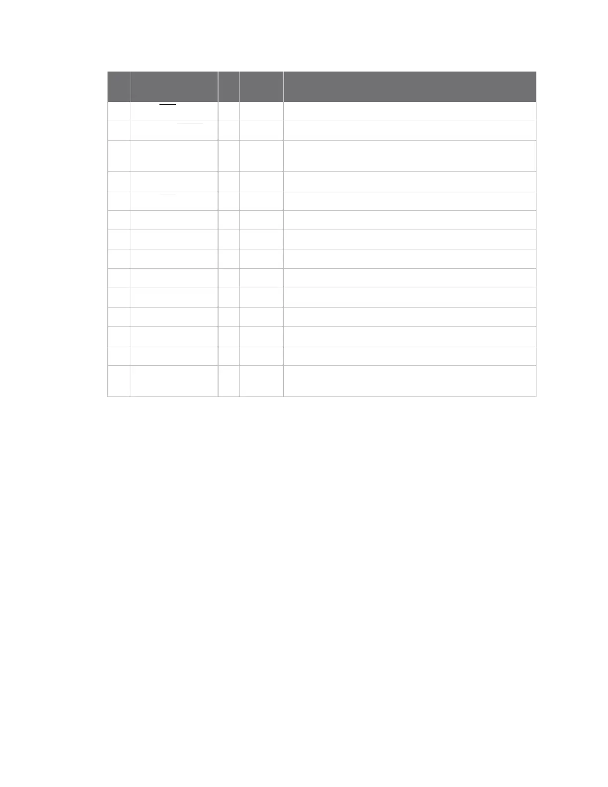
Pin Name I/O
Default
state Function
25
DIO7/CTS
I/O Output GPIO / UART Clear to Send Flow Control
26
DIO9/ON/SLEEP
I/O Output GPIO / Module Sleep Status Indicator
27
V
REF
- - Feature not supported on this device. Used on other XBee
devices for analog voltage reference.
28 DIO5/ASSOC I/O Output GPIO / Associate Indicator
29
DIO6/RTS
I/O Disabled GPIO / UART Request to Send Flow Control
30 DIO3/AD3 I/O Disabled GPIO / Analog Input
31 DIO2/AD2 I/O Disabled GPIO / Analog Input
32 DIO1/AD1 I/O Disabled GPIO / Analog Input
33 DIO0/AD0 I/O Input GPIO / Analog Input / Commissioning Pushbutton
34 [Reserved] - - Do not connect
35 GND - - Ground
36 RF_PAD I/O - RF connection for RF pad variant
37 [Reserved] - - Do not connect
38 GND - - Ground pad for heat transfer to host PCB. Located on the
underside of the XBee module.
Pin connection recommendations
The only required pin connections are VCC, GND, DOUT and DIN. To support serial firmware updates,
you should connect VCC, GND, DOUT, DIN, RTS, and SLEEP (DTR).