Hardware Pin signals
XBee®/XBee-PRO SX RF Module User Guide
21
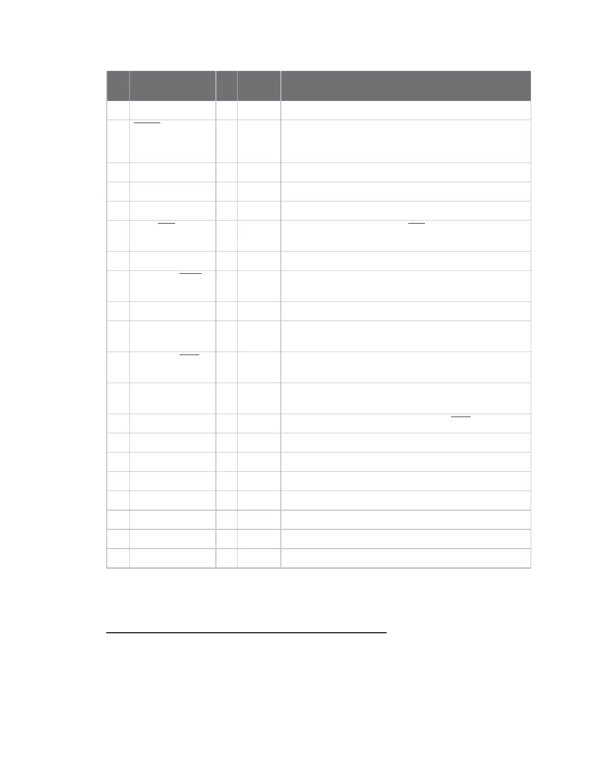
Pin Name I/O
Default
state Function
5 DIO12 I/O Disabled GPIO
6
RESET
I - Drive low to reset device. Do not drive pin high; pin may
only be driven open drain or low. Pin has an internal 20k
pullup resistor
7 DIO10/RSSI/PWM0 I/O Output GPIO / RX Signal Strength Indicator
8 DIO11/PWM1 I/O Disabled GPIO / Pulse Width Modulator
9 [Reserved] - - Do not connect
10
DIO8/DTR /SLEEP_
RQ
I/O Input
GPIO / Pin Sleep Control line (DTR on the development
board)
11 GND - - Ground
12
DO19/SPI_ATTN
O Output GPO / Serial Peripheral Interface (SPI)Attention or UART
Data Present indicator
13 GND - - Ground
14 DO18/SPI_CLK I/O
1
Input GPO / SPI clock
15
DO17/SPI_SSEL
I/O
2
Input GPO / SPI not select
16 DO16/SPI_MOSI I/O
3
Input GPO / SPI Data In
17 DO15/SPI_MISO O Output
GPO/SPI Data Out Tri-stated when SPI_SSEL is high
18 [Reserved] - - Do not connect
19 [Reserved] - - Do not connect
20 [Reserved] - - Do not connect
21 [Reserved] - - Do not connect
22 GND - - Ground
23 [Reserved] - - Do not connect
24 DIO4 I/O Disabled GPIO
1
Pins 14-16 are inputs in SPI mode only. In general purpose I/O pin mode you can only use them as digital
outputs.
2
Pins 14-16 are inputs in SPI mode only. In general purpose I/O pin mode you can only use them as digital
outputs.
3
Pins 14-16 are inputs in SPI mode only. In general purpose I/O pin mode you can only use them as digital
outputs.