AT commands I/O settings commands
XBee®/XBee-PRO SX RF Module User Guide
94
Parameter range
1, 2, 4 - 6
Parameter Description
0 Disabled
1
SPI_ATTN
2 N/A
3 N/A
4 Digital output low
5 Digital output high
6 UART data present indicator
Default
1
PD (Pull Direction)
The resistor pull direction bit field (1 = pull-up, 0 = pull-down) for corresponding I/O lines that are set
by the PR command.
Parameter range
0x0 - 0xFFFFF
Default
0xFFFFF
PR (Pull-up/Down Resistor Enable)
PR and PD only affect lines that are configured as digital inputs or disabled.
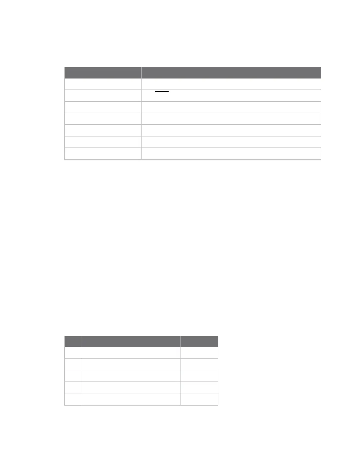
The following table defines the bit-field map for PR and PD commands.
The bit field that configures internal pull-up/down resistors status for I/O lines. If you set a PR bit to 1,
it enables the internal pull-up/down resistor, 0 specifies no internal pull-up/down. The following table
defines the bit-field map for both the PR and PD commands.
Bit I/O line Module pin
0 DIO4/AD4 24
1 DIO3/AD3 30
2 DIO2/AD2 31
3 DIO1/AD1 32
4 DIO0/AD0 33