Getting started with the XBee/XBee-PRO SX RF Module Development Kit XBee SX Development Board
XBee®/XBee-PRO SX RF Module User Guide
24
XBee SX Development Board
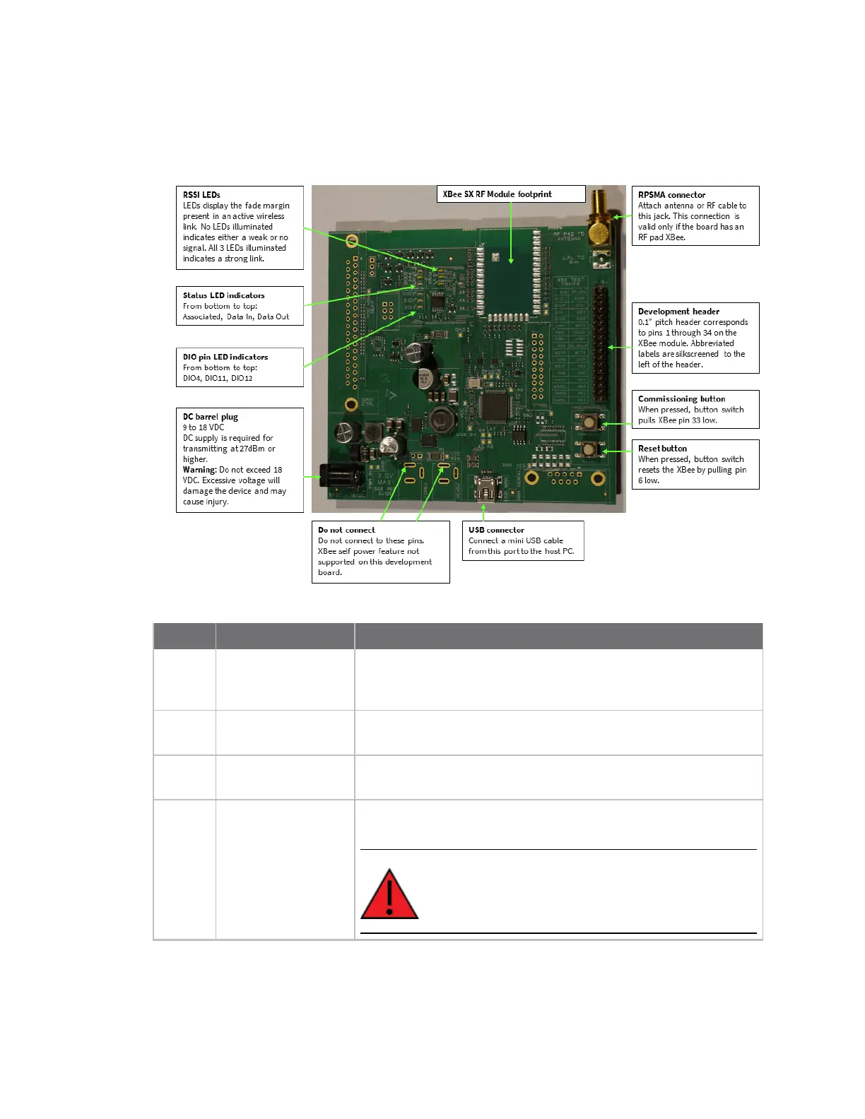
The following figure shows the XBee SX development board with onboard XBee-PRO SXRF pad
module and the table that follows explains the callouts in the picture.
Number Item Description
1 RSSILEDs LEDs display the fade margin present in an active wireless link. No
LEDs illuminated indicates either a weak or no signal. All three
LEDs illuminated indicates a strong link.
2 StatusLEDindicators From bottom to top: Associated, Data In, Data Out
3 DIO pin LED
indicators
From bottom to top: DIO4, DIO11, DIO12
4 DC barrel plug
9 to 18 VDC DC supply is required for transmitting at 27 dBm or
higher.
WARNING! Do not exceed 18 VDC. Excessive voltage
will damage the device and may cause injury.