71
CORN CRACKER INSTALLATION INSTRUCTIONS
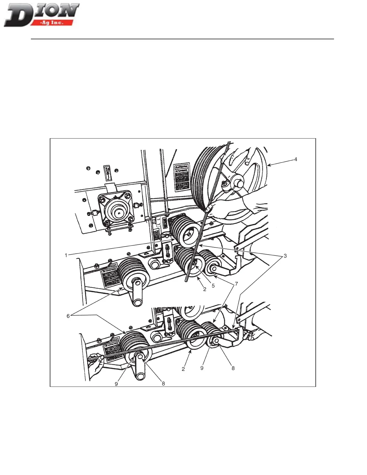
STEP 16 - FIGURE 91
First, align the upper sheave (item 1) and lower sheave
(item 2). Use a straight steel bar (item 3) and press it
against the driving sheave (item 4) as shown. Adjust
the sheaves (items 1 and 2) so that they touch the bar.
The adjustment of the sheaves (items 1 and 2) is per-
formed by sliding forward the sheave’s non-threaded
holes on the Q.D. bushing hub threaded holes. To slide
the sheaves backwards, use the sheave threaded holes.
The bolts (item 5) should be gradually screwed in se-
quence. For example: rst, second, and third bolts then
repeat this sequence.
THE WRENCH TORQUE for 1/4” bolts is 9 lbs-ft. (12
Nm).
Thereafter, align as close as possible the tightening
sheave (item 6) and the idler sheave (item 7) by press-
ing the steel bar (item 3) against the lower sheave (item
2) as shown. Adjust the sheaves (items 6 and 7) by re-
moving the shaft bolts (item 8) and by using the special
at washers (item 9) on either side. Securely tighten the
shaft bolts.
Figure 91
Manual No. F4117E987E V1.1