79
STEP 5 - FIGURE 101
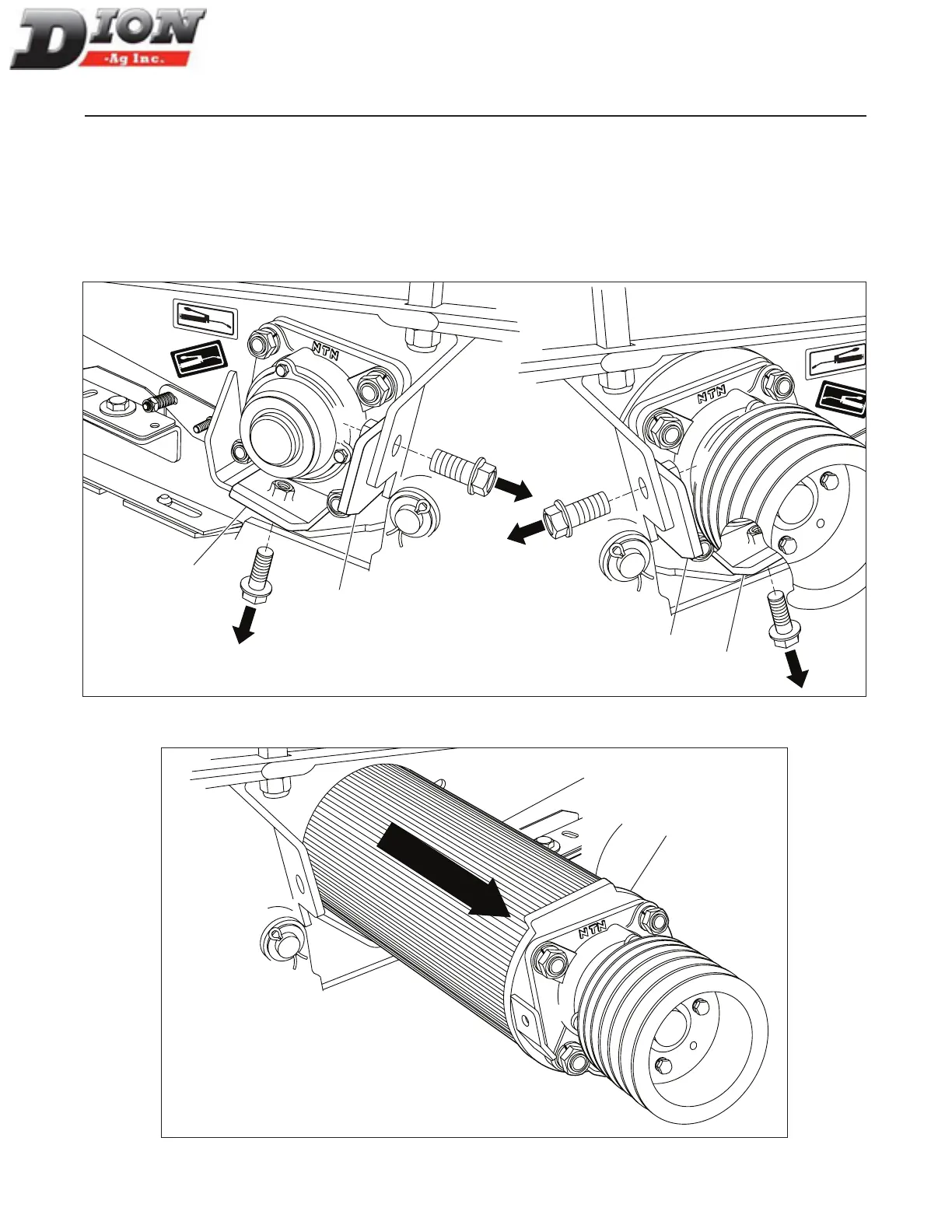
Unbolt the bearing support bracket (item 1) on the left-
hand side as well as the one on the right-hand side (item
2). Each support bracket is held in place by two 1/2” dia.
X 1” lg. ange bolts. The nuts are welded to the support
brackets (items 1 and 2).
STEP 6 - FIGURE 102
Remove the upper roll assembly (item 1).
NOTE: When installing the roll, clean both half bottom
plates well by removing any hay silage residue,
before sliding in the upper roll.
PARTIAL DISMANTLING OF THE CORN CRACKER FOR HAY CROP
1
1
2
2
Figure 101
1
Figure 102
Manual No. F4117E987E V1.1