ENGINE ELECTRICAL
-
Gharging System
8-233
7Ft
nnn
1.
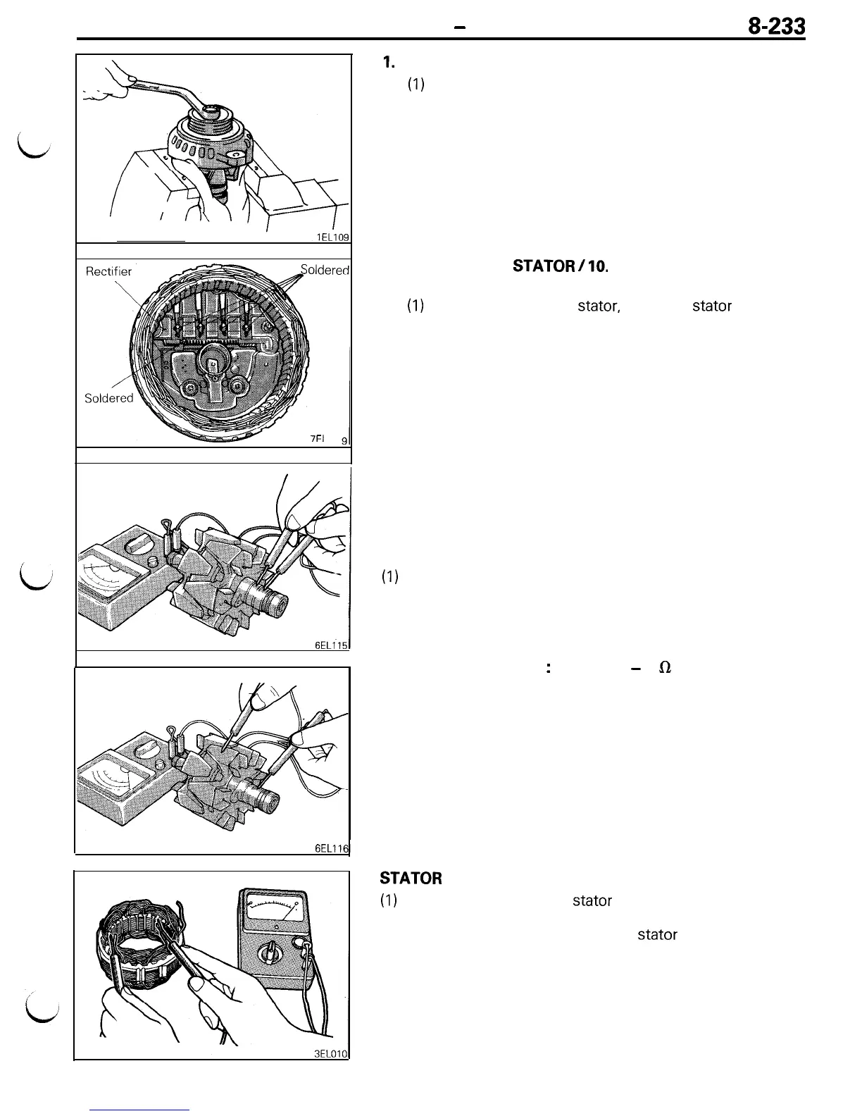
REMOVAL OF GENERATOR PULLEY
(1)
Clamp the rotor in a vise with soft jaws.
(2) After removing the nut, remove the pulley and front
bracket from the rotor.
7.
REMOVAL OF
STATOR
/
10.
REGULATOR AND BRUSH
HOLDER
(1)
When removing the
stator,
unsolder
stator
lead wire
from the main diode of the rectifier.
(2) When removing the brush holder, unsolder it from the
rectifier.
Caution
(1) When soldering or unsoldering, use care to
make sure that heat of soldering iron is not
transmitted to diodes for a long period. Finish
soldering or unsoldering in as short a time as
possible.
(2) Use care that no undue force is exerted to leads
of diodes.
INSPECTION
ROTOR
(1)
Check field coil for continuity. Check to ensure that there is
continuity between slip rings.
If resistance is extremely small, it means that there is a
short. If there is no continuity or if there is short circuit,
replace rotor assembly.
Resistance value
:
Approx 3
-
5
Ln
(2) Check field coil for grounding. Check to ensure that there is
no continuity between slip ring and core. If there is
continuity, replace rotor assembly.
STATOR
(1)
Make continuity test on
stator
coil. Check to ensure that
there is continuity between coil leads.
If there is no continuity, replace stator assembly.