8-410
CHASSIS ELECTRICAL
-
Rear Window Defogger
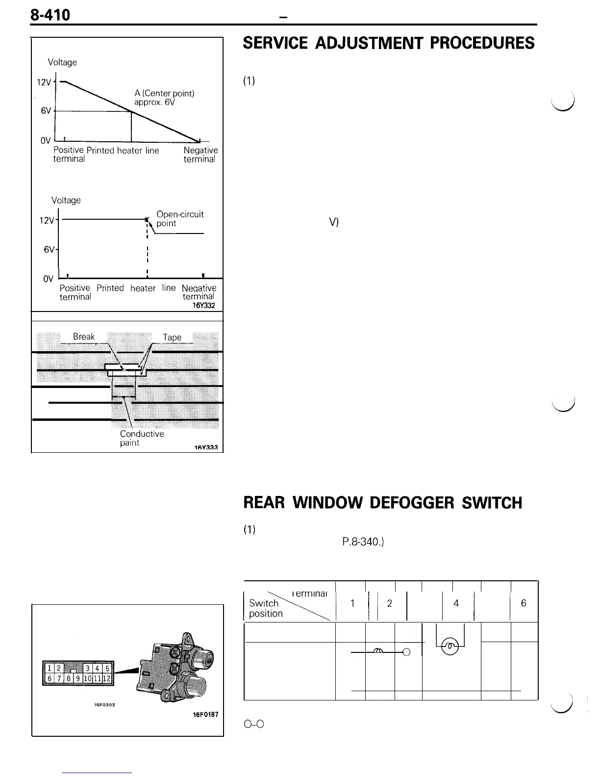
Normal characteristic curve
SERVICE
ADJUSTMENT
PROCEDURES
Voltage
,‘..!x
Positive
Printed
heater
line
terminal
Negative
terminal
Abnormal characteristic curve
Voltage
12v
1
Open-circuit
yfwnt
I
6V
1
cd
’
I
L
1
Positive
Printed
heater
line
Negative
terminal
terminal
16Y332
7‘
Conductive
-_:-A
pdllll
l(iV333
16FO187
THE PRINTED-HEATER LINES CHECK
(1)
Run engine at 2,000 rpm. Check heater element with
battery at full.
(2) Turn ON rear window defogger switch. Measure heater
element voltage with circuit tester at rear window glass
center A.
Condition good if indicating about 6 V.
(3) If 12 V is indicated at A, there is a break in the negative
terminals from A.
Move test bar slowly to negative terminal to detect where
voltage changes suddenly (0 V).
(4) If 0 V is indicated at A, there is a break in the positive
terminals from A. Detect where the voltage changes
suddenly (12
V)
with the same method described.
THE PRINTED-HEATER LINES REPAIR
REQUIRED MATERIALS
l Thinner
l
Lead-free gasoline
l Tape
l
Fine brush
l Conductive paint
(1) Clean disconnected area with lead-free gasoline. Tape
along both sides of heater element.
(2) Mix conductive paint thoroughly. Thin the required amount
of paint in a separate container with a small amount of
thinner and paint break three times at 15 minute intervals.
(3) Remove tape and leave for a while before use (circuit
complete).
d
(4) When completely dry (after 24 hours) finish exterior with a
knife.
Caution
Clean glass with a soft cloth (dry or damp) along
defogger heater element.
REAR
WINDOW
DEFOGGER
SWITCH
(1)
Remove rear window defogger switch from the meter
bezel. (Refer to
P.8-340.)
(2) Operate the switch and check the continuity between the
terminals.
I!@ki/
1
1
12
1
3
14
/
5
16
OFF
ON
0
m
ILL
IND
0
0
NOTE
GO
indicates that there is continuity between the terminals.
\
d’