CHASSIS ELECTRICAL
-
Theft-alarm System
8-427
IO.
HORN ACTIVATION CIRCUIT
:
i
F”SlBLE
LINK
m
1
m
I
;:
0
PSPl
,CATED
101
z
m
m
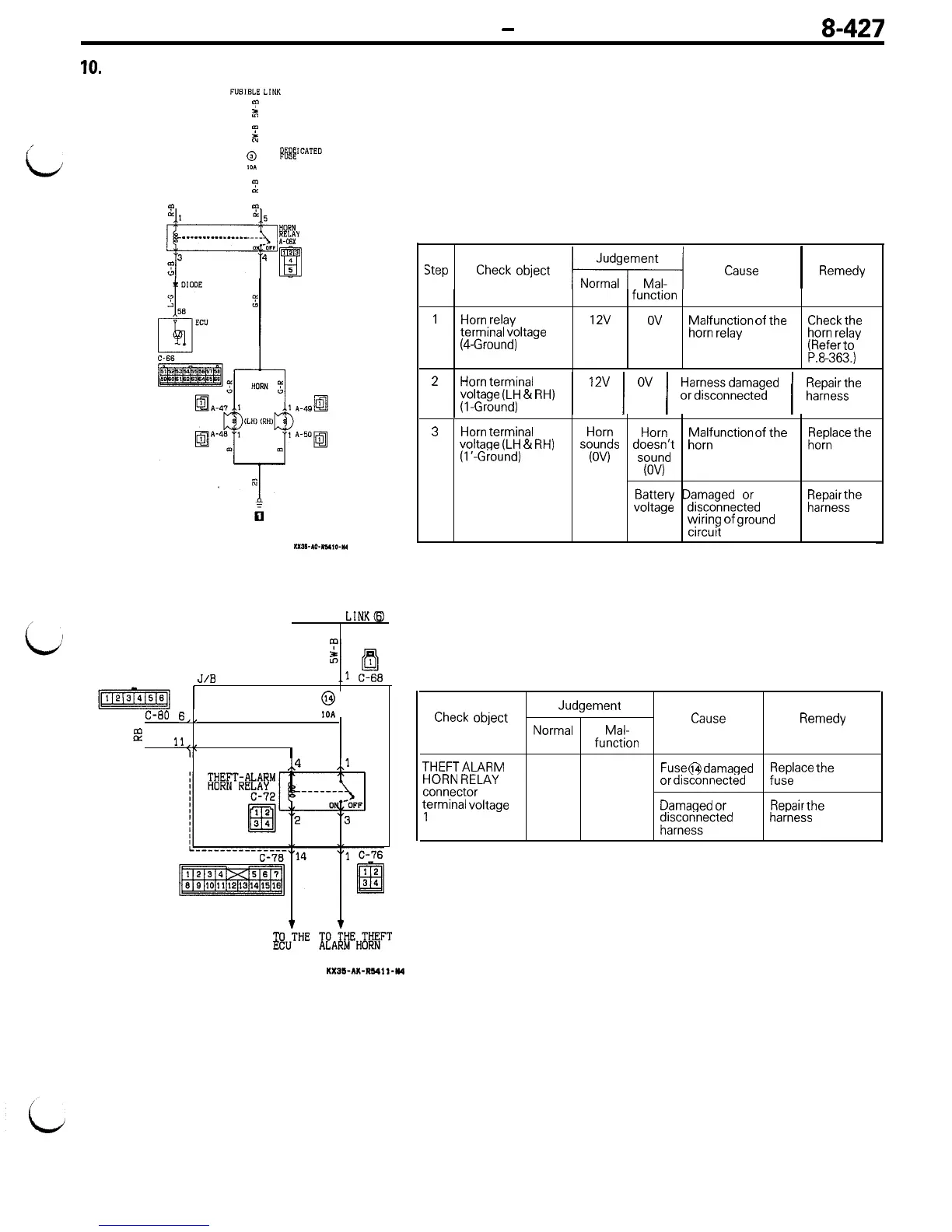
Description of operation
The ECU transistor is turned ‘ON if the vehicle door, etc. are
opened without use of the key.
This energizes the horn relay to activate the horn.
Checking the horn activation circuit (Disconnect the connector
of the ECU, then short-circuit terminal connector No. 58, and
h
t
FP
________________
-ywIrF
f&
3
123
:
4
4
RI
5
IXSI-m-IY,o-U
activate the horn relay.)
Step
Check
object
IsI
Cause
1
Remedy
function
1
Horn
relay
12v
ov
Malfunction of the
Check
the
terminal voltage
(4.Ground)
horn
relay horn
relay
(Refer
to
P.8-363.)
2
Horn
terminal
voltage
(LH
&
RH)
(l-Ground)
1
1~
1
OV
/
~fygda;gyd
/
;;r;;;he
3
Horn
terminal
Horn
Horn
Malfunction of the
voltage
(LH
&
RH)
sounds
doesn’t
horn
Replace
the
horn
(I’-Ground)
(OV)
sound
(OV)
Battery
Damaged
or
voltage disconnected
wiring of
ground
circuit
Repair
the
harness
11. THEFT ALARM HORN RELAY POWER-SUPPLY CIRCUIT
Description of operation
FUSIBLE
LINKQ
J/B
@
c-80
6,,
,OA
B
ll,,
I‘
I
,,4
,,l
T T
6
hTHE
IE!A%I~~%J~~
Power voltage is always supplied to the theft alarm horn relay.
Checking the horn relay power-supply circuit (Disconnect the
theft alarm horn relay)
Check
object
Judgement
Cause
Normal Mal-
Remedy
function
THEFTALARM
HORN
RELAY
connector
terminal voltage
1
12v ov
Fuse
@ damaged
or
disconnected
fRuesP,lace
the
Damaged
or
Repair
the
;zsFeTsected harness
KX35-AK-R2411-K4