Adjusting the thread system
Service instructions 967 - 00.0 - 12/2014
71
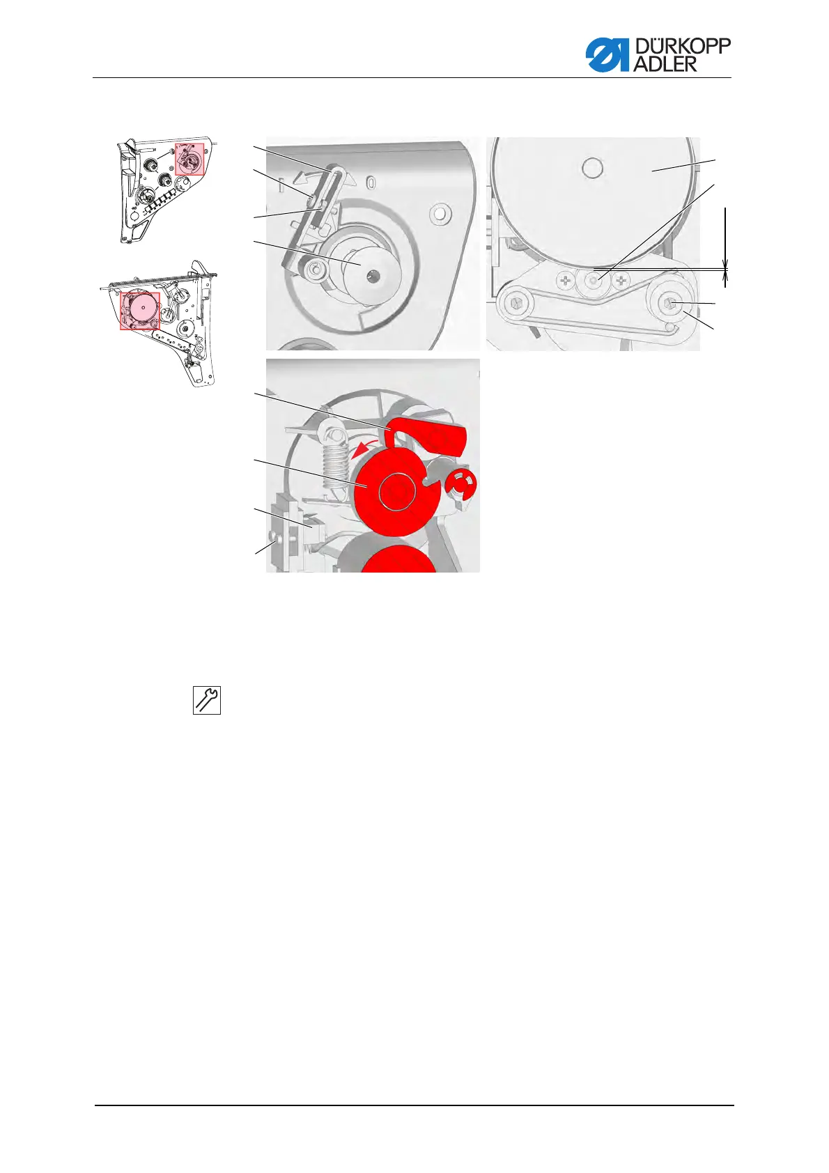
Figure 49: Adjusting the winder – part 2
Setting steps
1. Turn the winder lever (1) to the position 0 (winder switched off).
2. Loosen the screw (10).
3. Turn the eccentric (9) so that there is a gap of 0.5 mm between the
friction disc (12) and rubber pulley (11).
4. Tighten the screw (10).
5. Loosen the screws (8).
6. Adjust the position of the microswitch (7).
7. Tighten the screws (8).
8. Turn the blocking cam (6) in the direction of the arrow and switch on the
winder so that the blocking lever (5) rests on the outer diameter of the
blocking cam (6).
The microswitch must not switch off (a clicking within the microswitch
indicates when it switches off).
9. Turn the winder shaft until the blocking lever (5) engages in the recess
in the blocking cam (6).
In this position the microswitch (7) must switch the motor off. If it does
not do this, correct the position of the microswitch.
(1) - Bobbin lever
(2) - Screw
(3) - Locknut
(4) - Bobbin
(5) - Blocking lever
(6) - Blocking cam
(7) - Microswitch
(8) - Screws
(9) - Eccentric
(10) - Screw
(11) - Rubber pulley
(12) - Friction disc
ཱ
ི
ཱི
ུ
ཱུ
ཷ
ླྀ
ཹ
ྲྀ
ེ
0.5 mm
 Loading...