Adjusting the thread cut-off
Service instructions 967 - 00.0 - 12/2014
77
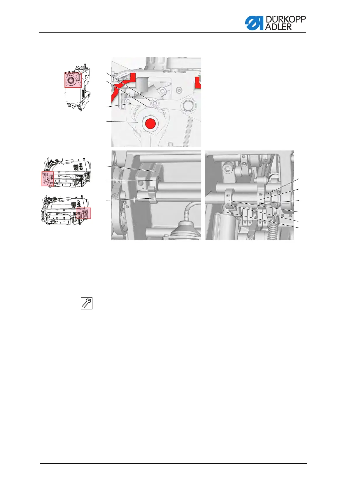
Figure 52: Basic setting of the thread cutter
Setting steps
1. Undo the screws (7) of the stop lever (6) and the screws (9) of the
lever (10).
2. Secure the screws (11) for the lower lever (12) to the flat on the lower
shaft (13) and tighten both screws.
3. Put the handwheel into the 80° position page 20.
4. Lightly tighten the screws (7) of the stop lever (6), to that the stop lever
(7) can be turned on the lower shaft (13) with a slight frictional torque.
5. Insert a 0.1 mm feeler gage (2) between the control cam (4) and roller (1).
6. Press the upper lever (3) down and at the same time turn the stop
lever (6) until it contacts the baseplate (5).
7. Tighten both screws of the eccentric lever (7).
8. Check the distance between the roller (1) and control cam (4), and adjust
it if necessary.
9. Turn the piston (8) until it is just short of the stop (approx. 0.5 mm dis-
tance).
10.Tighten the screws (9) for the lever (10).
(1) - Roller
(2) - Gage
(3) - Upper lever
(4) - Control cam
(5) - Base plate
(6) - Stop lever
(7) - Screws
(8) - Piston
(9) - Screws
(10) - Lever
(11) - Screws
(12) - Lower lever
(13) - Lower shaft
ཱ
ི
ུ
ཱུ
ཷ
ླྀ
ཹ
ྲྀ
ེ
ཱི
ཻ
ོ
 Loading...