Working basis
Service Instructions 967 - 02.0 - 12/2015
19
3.6 Locking the machine in place
For some settings, the machine has to be locked in place. To do this, the
locking peg from the accessory pack is inserted into a groove on the arm
shaft crank to block the arm shaft.
There are 2 securing positions:
• Posi
tion 1: Loop stroke position
• 5 mm end in the large groove
•
Setting the loop stroke and needle bar height
• Posi
tion 2: Handwheel zero position
• 3 mm end in the small groove
•
Setting the handwheel position and checking the bottom dead
center for the needle bar
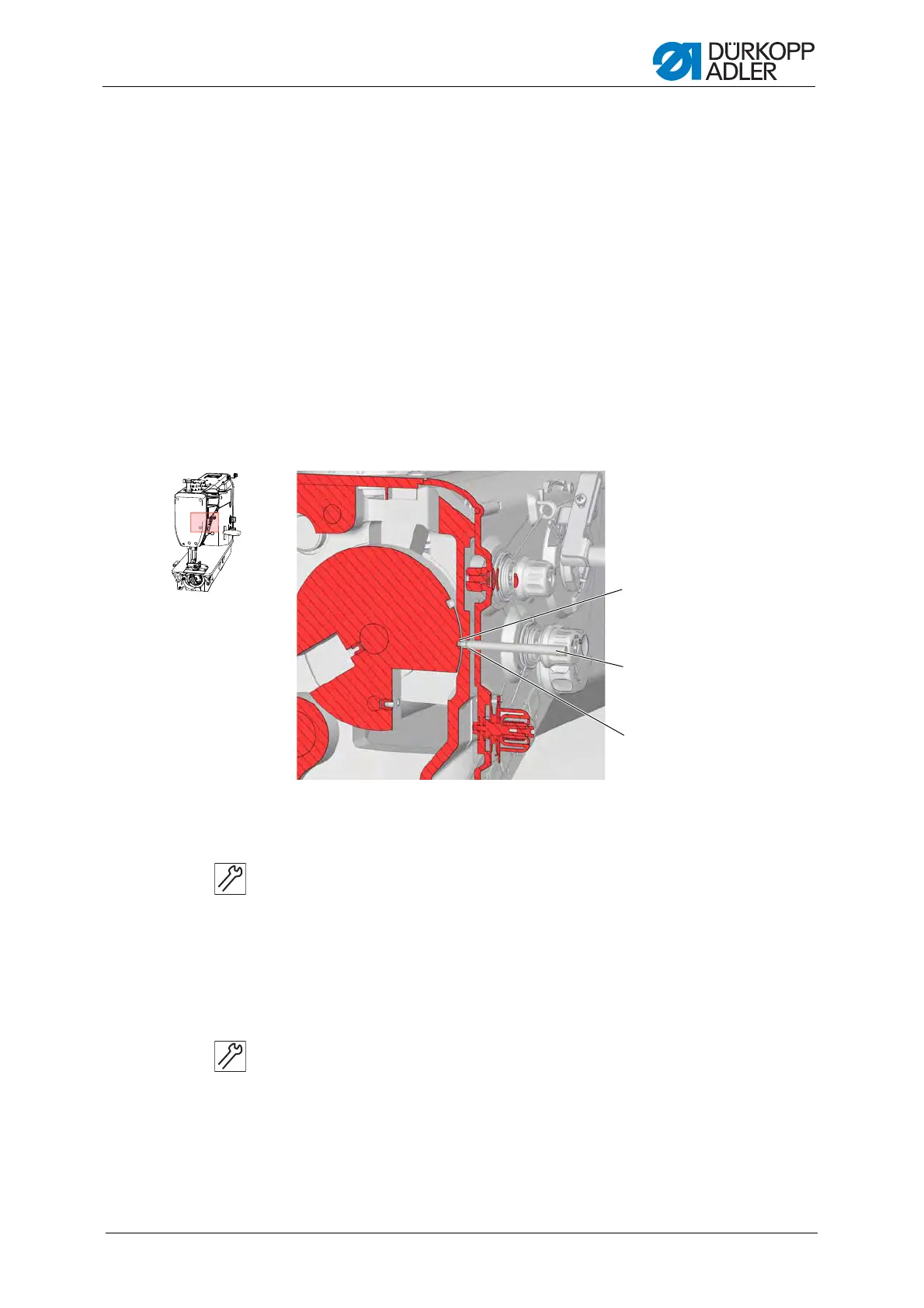
Fig. 12: Locking the machine in place
Locking the machine in place
1. Turn the handwheel until the appropriate groove (1) is in front of the
locking opening
(3):
• Small groove at handwheel position 180°
• Large groove at handwheel position 200 – 205°
2. Insert the arresting pin (2) with the appropriate end into the groove (1).
Removing the lock
1. Pull the locking peg (2) out of the groove (1).
(1) - Groove
(2) - Locking peg
(3) - Locking opening
①
②
③
 Loading...