Adjusting the foot stroke
66
Service Instructions 967 - 02.0 - 12/2015
3. Turn the lift lever (3) such that there is a clearance of 0.3 to 0.5 mm between
the lift lever (3) and the drive dog (4).
4. Tighten the screw (2).
12.2 Adjusting the foot stroke generated by the pneumatic
cylinder
Proper setting
The stroke of the presser foot generated by the pneumatic cylinder is
30 mm.
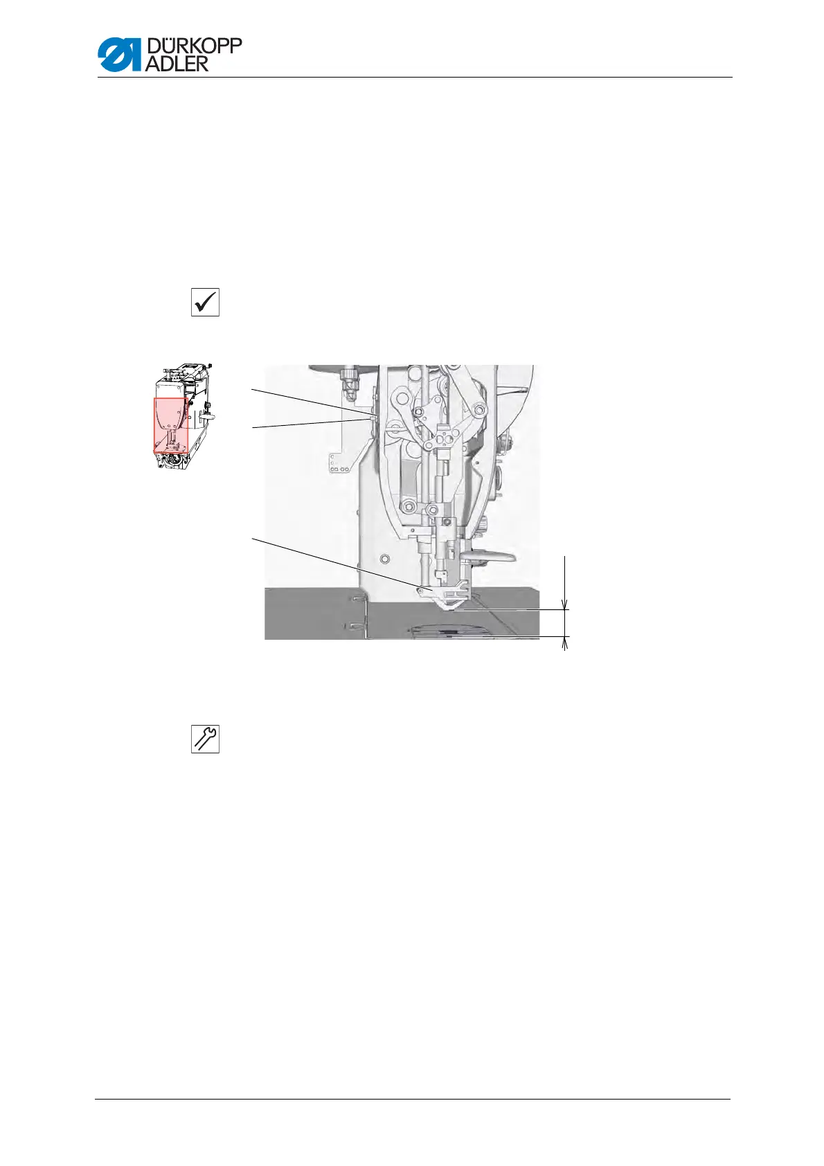
Fig. 47: Adjusting the stroke of the feet generated by the pneumatic cylinder
Setting steps
1. Put the handwheel into the 0° position ( p.
20). The presser foot (3)
rests on the throat plate.
2. Loosen the counternut (1).
3. Activate the pneumatic lifting of the foot
( see Operating Instructions 967).
The presser foot (3) is lifted.
4. Turn the screw (2) until the height of the presser foot (3) is 30 mm above
the throat plate.
5. Tighten the counternut (1).
(1) - Counternut
(2) - Screw
(3) - Presser foot
①
②
③
30 mm
 Loading...