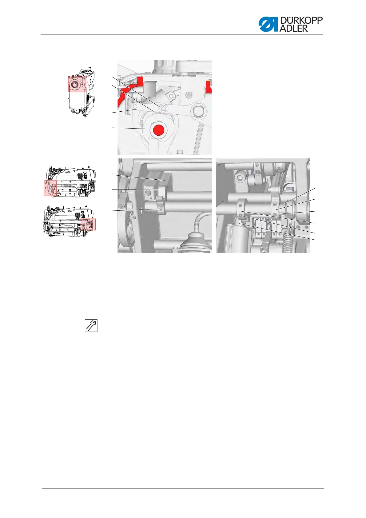
Adjusting the thread cutter
Service Instructions 967 - 02.0 - 12/2015
77
Fig. 53: Basic setting of the thread cutter
Setting steps
1. Loosen the screws (7) of the stop lever (6) and the screws (9) of the
lever (10).
2. Secure the screws (11) for the lower lever (12) to the flat on the lower
shaft (13) and tighten both screws.
3. Put the handwheel into the 80° position ( p. 20).
4. Lightly tighten the screws (7) of the stop lever (6) such that the stop
lever (7) can be turned on the lower shaft (13) with a slight frictional
torque.
5. Insert a 0.1 mm feeler gage (2) between the control cam (4) and roller (1).
6. Press the upper lever (3) down and, at the same time, turn the stop lever
(6) until it contacts the base plate (5).
7. Tighten both screws of the stop lever (7).
8. Check the distance between the roller (1) and control cam (4), and adjust
it if necessary.
(1) - Roller
(2) - Gage
(3) - Upper lever
(4) - Control cam
(5) - Base plate
(6) - Stop lever
(7) - Screws
(8) - Piston
(9) - Screws
(10) - Lever
(11) - Screws
(12) - Lower lever
(13) - Lower shaft
①
②
③
⑤
⑥
⑧
⑨
⑩
⑦
⑪
④
⑫
⑬
 Loading...