6. Function blocks
6.1 Manufacturer function blocks
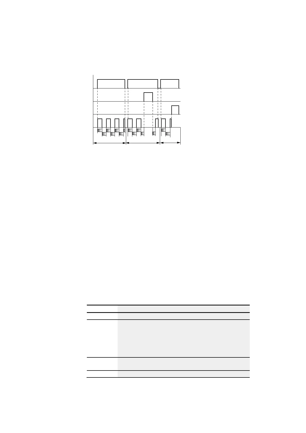
How the timing relay works with the flashing operating mode, synchronous and
asynchronous
t
1
+ t
2
= t
s2
t
s1
t
s1
t
s1
t
s2
t
s2
t
s1
t
s1
t
s2
t
s2
A B
1
2
4
3
t
t
s1
t
s2
C
Fig. 151: Signal diagram timing relay, single pulse
1: Trigger coil T..EN
2: Stop coil T..ST
3: Reset coil T..RE
4: Switching contact (N/O contact) T…Q1
Range A: The relay flashes for as long as the trigger coil is activated.
Range B: The stop coil interrupts the timing out of the set time.
Range C: The reset coil resets the relay.
Other
Retention
Selected timing relays can be run with retentive actual values. If a timing relay is
retentive, the actual value is retained when the operating mode is changed from RUN
to STOP and when the power supply is switched off.
When the control relay is restarted in RUN mode, the timing relay continues with the
retentively stored actual value.
In the Project view, go to the System settings tab and select the timing relays, out of
T1 through T32, that should be run with retentive values. The retentive actual value
requires 4 bytes of memory.
Operand Description
Constant
0.. to 99:59 (time range: "M : S"/"H : M") or 0 - 99.99 (time range: "S")
C
Output of a counter relay (e.g. C3QV)
If the counter actual value is greater than the maximum permissible set-
point of the configured time range, the setpoint will be limited to this max-
imum value.
Example: You have configured the time range M: S and the counter actual
value is 31333. The device limits the setpoint to 5999 min.
IA
Note the relationship described below between the permissible analog
value and the timing relay setpoint.
T
Output of a timing relay (e.g. T4QV).
282
easyE402/24 MN050009ENEaton.com