6. Function blocks
6.1 Manufacturer function blocks
How the timing relay works with the single pulse operating mode with and
without random times
A B
t
1
+ t
2
= t
s
t
s
t
s
C
1
2
4
3
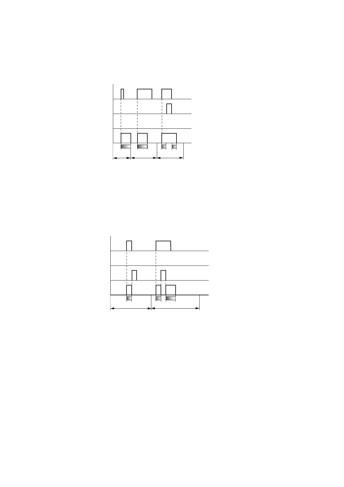
Fig. 149: Signal diagram timing relay, single pulse 1
1: Trigger coil T..EN
2: Stop coil T..ST
3: Reset coil T..RE
4: Switching contact (N/O contact) T…Q1
Range A: The trigger signal is short and is lengthened.
Range B: The trigger signal is longer than the set time.
Range C: The stop coil interrupts the timing out of the set time.
Fig. 150: Signal diagram timing relay, single pulse 2
• Range D: The reset coil resets the timing relay.
Range E: The reset coil resets the timing relay. The trigger coil is still energized after the reset coil is dis-
connected, whilst the delay time runs down..
easyE402/24 MN050009ENEaton.com
281