6. Function blocks
6.1 Manufacturer function blocks
Assigning operands Bit outputs
Q – Bit output
x
I – Bit input of a FB
x
2)
Only on projects with ≥ 2 base devices on NET
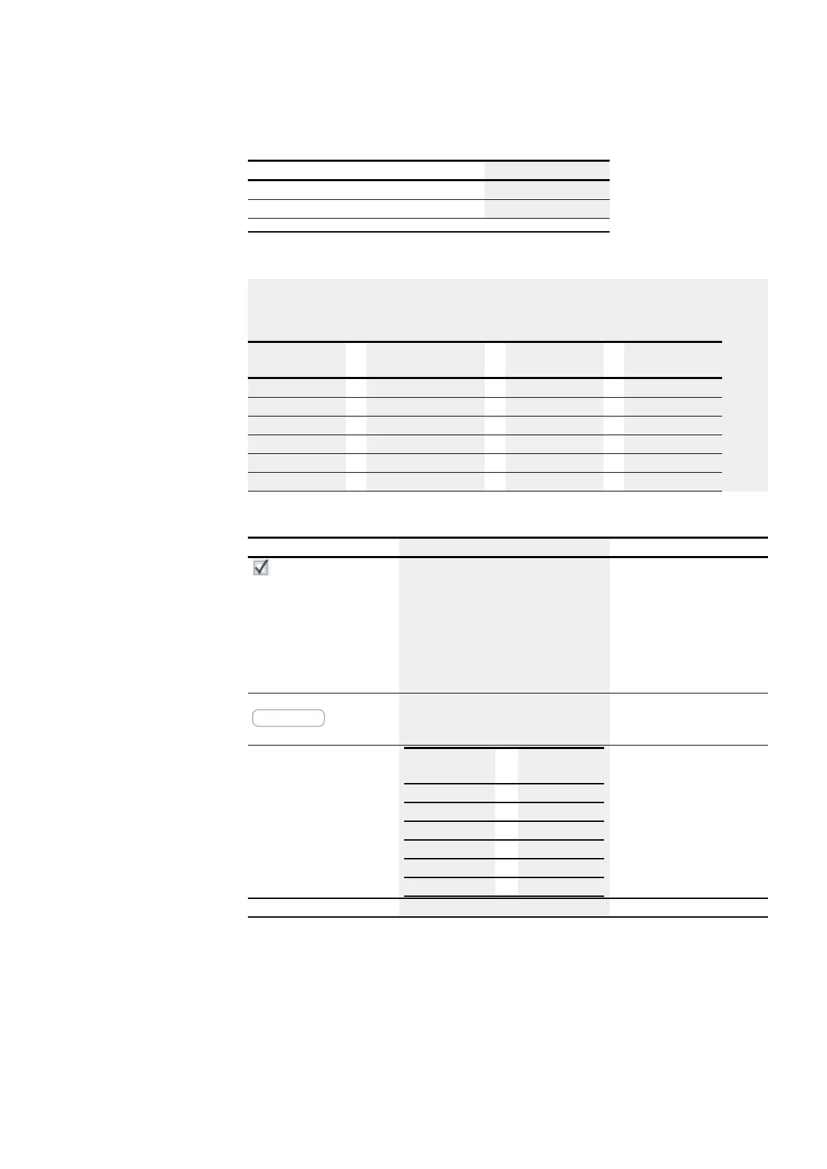
Example with CF01 with 50 Hz at the input
There is a square wave signal with a frequency of 50 Hz at device input I01. Outputs
QV and QF of function block CF01 will have the following values depending on the
chosen measuring interval:
Measuring inter-
val
QV QF f an I01
0.1s
5
500
50 Hz
0.5s
25
500
50 Hz
1.0s
50
500
50 Hz
2.0s
100
500
50 Hz
5.0s
250
500
50 Hz
10.0s
500
500
50 Hz
Parameter set
Description Note
Function block release
by EN is necessary
If this checkbox is enabled, the state of func-
tion block input EN will be evaluated. If the
checkbox is disabled instead, the function
block will be enabled and function block
input EN will not do anything.
This parameter ensures that
when existing programs are
copied, the functionality of
the function blocks that are
carried over will be retained.
The parameter will be auto-
matically set to 0 or 1 depend-
ing on the function block.
Parameter display
+ Call enabled
Constants can be edited on the device, as
can function block parameters when using
the EDP programming language.
Measuring interval
Measuring inter-
val
Maximum
value at QV
0.1s
500
0.5s
2 500
1.0s
5 000
2.0s
10 000
5.0s
25 000
10.0s
50 000
The longer the measuring
interval, the smaller the fre-
quency being measured can
be.
Simulation possible
easyE402/24 MN050009ENEaton.com
313
 Loading...


