6. Function blocks
6.1 Manufacturer function blocks
Other
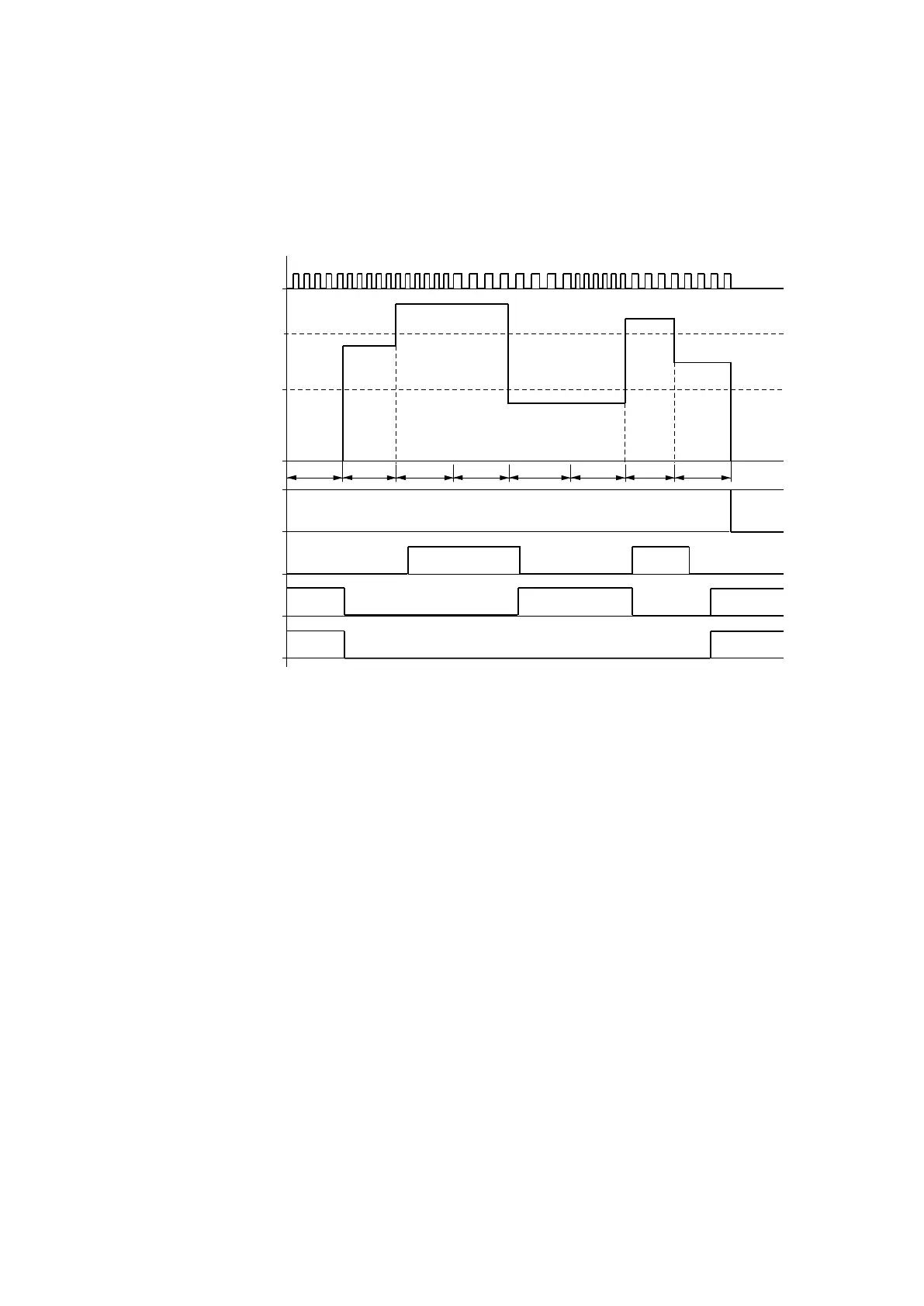
Signal diagram
Fig. 172: Signal diagram of frequency counter
1: One of the device inputs I01 to I04
2: Upper threshold value SH
3: Lower threshold value SL
4: Enable CF..EN
5: Function block output (N/O) OF: Upper threshold value exceeded
6: Function block output (N/O) FB: Lower threshold value undershot.
7: Function block output (N/O) ZE: If actual value equal to zero
8. tg: gate time ( = measuring interval) for the frequency measurement
The first measurements are made after the function block input EN enable signal has been activated.
After the gate time has expired, the value is output at the block outputs QV and converted to QF. The con-
tacts OF, FB and ZE are set in accordance with the measured frequency. If the EN enable signal is
removed, the output value is set to zero.
Retention
The frequency counter does not have any retentive actual values since the fre-
quency is continuously remeasured.
314
easyE402/24 MN050009ENEaton.com

 Loading...


