STP-iS2207 Series Turbomolecular Pump
MT-89E-001-C
Page 138
7
SAFETY FUNCTIONS
7.6 Troubleshooting
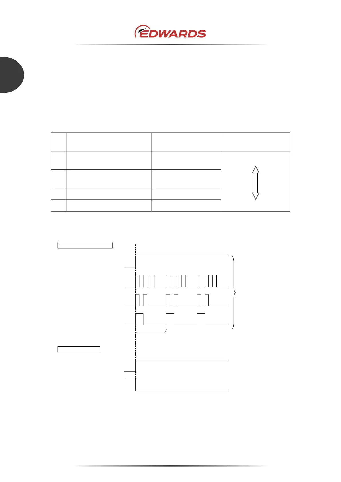
7.6.1 Indication of "FAILURE" LED (red)
The flashing pattern of the "FAILURE" LED (red) differs depending on the type of abnormality/error.
When two or more failures are detected simultaneously, a high-priority failure is indicated. Also, the
failure signal is output from the "X2 REMOTE" connector. If an abnormality/error is found, take
measures in accordance with Table 38 to Table 42. DO NOT perform operations not mentioned in
Table 38 to Table 42.
No
Failure
"FAILURE" LED
indication
Priority
1
Power Failure
Overspeed, and other
Steady red
High
2
MOTOR Overheat
CNT Overheat
3 flashes in red
3
DRV Overload 2 flashes in red
4
Disturbance 1 flash in red Low
Table 37 - Priority of failure signal
1 cycle
Disturbance
(1 flash in red)
OFF
↓Failure detection
"FAILURE" LED indication
X2 REMOTE output
ON
DRV Overload
(2 flashes in red)
MOTOR Overheat
CNT Overheat
(3 flashes in red)
Corresponding to
failure type
OFF
OFF
ON
ON
ON
OFF
FAILURE N.O OUT
(8)–(21)
OFF
ON
Power Failure
Overspeed
(steady in red)
ON
OFF
FAILURE N.C OUT
(9)–(21)
Figure 52 - Failure output
Note: The STP-Link (optional accessory) and the display unit (optional accessory) display an error
as a message. Also, the errors being detected can be read via serial communication.
 Loading...