User Manual Chapter 2
GFK-1742F Jan 2020
System Overview 19
2.2 Assembling the Motion Mate DSM314 System
2.2.1 General Guidelines
•
Always make sure that the connectors lock into the sockets. The connectors are
designed to fit only one way. Do not force them.
•
Do not overlook the importance of properly grounding the DSM314 system
components, including the DSM314 faceplate shield ground wire. Grounding
information is included in this section.
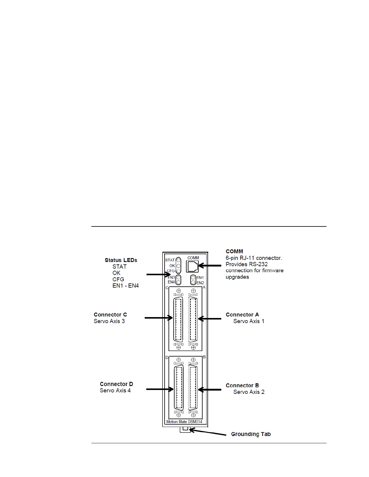
All user connections, except for the grounding tab, are located on the front of the DSM314
module. The grounding tab is located on the bottom of the module. Refer to the figure
below.
For instructions about installation of the DSM314 when IEC and other standards must be
observed, see Installation Requirements for Conformance to Standards, GFK-1179.
2.2.2 Motion Mate DSM314 Connections
Figure 6 provides an overview of the faceplate and labels on the DSM314 module. For
additional information and a complete connection diagram, please refer to chapter 3,
Installing and Wiring the Motion Mate DSM314.
Figure 6: Face Plate Connections on the Motion Mate DSM314 Motion Control System