User Manual Appendix B
GFK-1742F Jan 2020
DSM314 Communications Request Instructions 396
The order in which these instructions are sent is critical, so the Command Block for each type
of COMM REQ should be programmed exactly as instructed later in this appendix. In the
figure above, the DSM module is shown in the CPU rack and communications occur over the
host controller backplane. If the DSM module is located in an expansion or remote rack, the
commands and data are sent over the CPU rack’s backplane, through the expansion or
remote cable to the rack containing the DSM module, and across that rack’s backplane to
the DSM.
At the conclusion of every request, the host controller CPU reports the status of the request
to the Status Word, which is a location in host controller memory that is designated by the
Status Word Pointer in the Command Block.
B-2 The COMM REQ Ladder Instruction
This section discusses the COMM REQ instruction in general. More information is provided
in the PACSystems CPU Reference Manual, GFK-2222 and the Series 90-30/20/Micro PLC
CPU Instruction Set Reference Manual, GFK-0467. The Communications Request begins
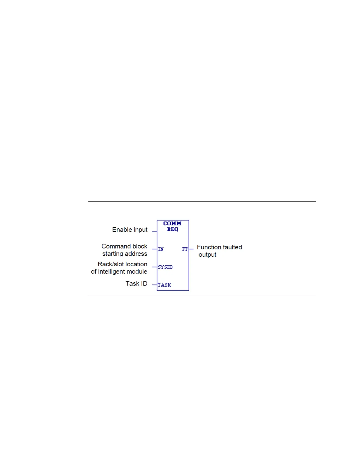
when the COMM REQ Ladder Instruction is activated. The COMM REQ ladder instruction has
four inputs and one output:
Figure 182: COMM REQ Ladder Instruction
Enable Input: Must be Logic 1 to enable the COMM REQ Instruction. It is recommended that
the enabling logic be a contact from a transition (“one-shot”) coil.
IN: The memory location of the first word of the Command Block. It can be any valid address
in word-type memory (%R, %AI, or %AQ).
SYSID: A hexadecimal value that gives the rack and slot location of the module that the
COMM REQ is targeting. The high byte (first two digits of the hex number) contains the rack
number, and the low byte contains the slot number. The table below shows some examples
of this:
SYSID Examples